Types of the Shipboard Ventilation Systems

The interior environment aboard ship is controlled to provide an atmosphere which is agreeable to the operating personnel, machinery and equipment, cargo and ship stores, and passengers. The environment may be modified by means of ventilation, heating, cooling, and dehumidification or by any combination of these means. Additionally, the elements of noise and vibration must be controlled. The means of controlling these environmental factors must be as reliable, simple, and maintenance free as practical, consistent with the desired results.
Ventilation is the process used to provide fresh outside air to various spaces within the ship. The air is distributed by means of a duct network and suitable weather openings in the ship's envelope. The type of ventilation used depends upon the nature of the space and the service of the ship. The fresh air may be supplied by natural draft or mechanical means and is provided for the removal of heat, noxious or explosive vapors, and to assure an adequate supply of oxygen to personnel. The quantity of air required for each space ventilated is determined by heat transfer or empirical calculations.
Types of Systems
There are two basic types of ventilation systems; natural and mechanical. In the natural ventilation system, air movement is created by the difference in temperature and density of inside and outside air and the trimming of cowls or scoops toward the wind.
A typical system consists of a suitably weather-protected inlet or outlet, a duct to the area served and distribution branch ducts with terminals designed to suit the supply or exhaust air function required. The mechanical ventilation system may be of the mechanical-supply/natural-exhaust type, the mechanical-exhaust/natural-supply type, or the mechanical-supply/mechanical-exhaust type, depending upon the location of the fan or fans within the system. In general, the mechanical-supply/natural-exhaust type system will maintain a slight positive pressure within the spaces 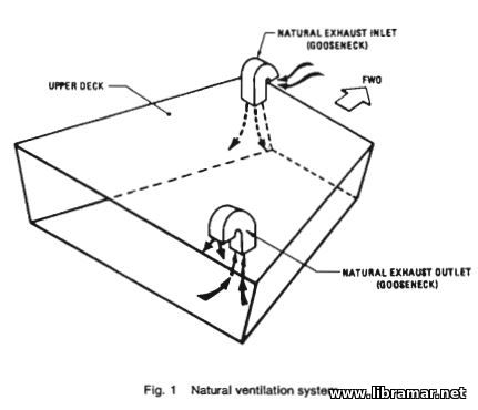 served.
The natural-supply/mechanical-exhaust type system will maintain a slight negative pressure within the spaces served; this type of system is used in spaces such as galleys, toilets, and pantries where a positive pressure might dispel the heat and odors into adjacent spaces. The mechanical-supply/mechanical-exhaust type system may produce either a slight positive or negative pressure within the spaces served depending upon the relative ratings of the supply and exhaust fans.
Special consideration must be given to ventilation systems which serve spaces having the potential for containing hazardous vapors. Examples of such spaces are the cargo pump room on tank vessels, the compressor room on liquefied gas carriers, and passageways in way of the cargo tanks on liquefied gas carriers. The relative densities of air and the vapor to be handled determine the locations of the supply and exhaust terminals.
Design Criteria
Temperature rise is the maximum difference between exhaust air and supply air temperatures. Maximum air change means the supply of a quantity of air equal to the space volume in the stated number of minutes. In designing a ventilation system, the aim of the designers should be to run the ducts in as nearly a straight line as possible, avoiding sharp bends, abrupt changes in duct sizes or shapes, and all other construction which may cause excessive pressure losses. It is seldom possible to achieve an ideal duct system in ship installations due to structure limitations, low overhead heights, and interferences with piping and other systems.
Other constraints are imposed by requirements for watertight subdivision and damage control as well as to prevent ventilation ducts from reducing fire resistance by passing smoke and flame. Cross-sectional areas of ducts should be 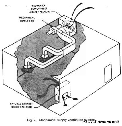 large enough to permit the air to flow at moderate velocities to avoid power waste and to reduce noise. The following maximum duct velocities rep¬resent good practice; in areas where quiet operation is essential, 10 m/s, and in areas where quiet operation is not essential 18 m/s. Sometimes obstructions are found during the installation of the ductwork and about 10 percent of the total fan pres¬sure should be reserved in the system for these additional losses.
Design of Duct Fittings
Good design can contribute much to the economy of system operation. Abrupt changes in duct sizes or indirection of airflow are always to be avoided. Abrupt expansions are particularly bad, since as much as five percent of the total available fan pressure can be lost in a single expansion. Elbows should be designed for smooth airflow. It is desirable to make the throat radius of the elbow equal to the dimension of the duct in the plane of the bend. Where this is impossible and a shorter radius is required, splitters should be added in these elbows. Where conditions require square elbows, curved turning vanes should be provided.
When smaller ducts are taken off the main supply duct to serve individual spaces, a division of the main duct is the most desirable method and is based on the proportional division of air; e.g., the air quantity is divided in proportion to the area of the duct. Where headroom and structural requirements do not allow this arrangement, and for small air quantities, branch takeoffs may be used; e.g., small ducts connected into the main duct at a 30-degree angle from the direction of airflow in the main duct. It should be recognized, however, that these branch takeoffs create a loss in the main duct. A series of such branches may generate sufficient loss in the system to require an increase in fan horsepower.
System Balance
All systems should be checked for proper air delivery after installation is complete. Usual requirements are a minimum of 90 percent of design air quantity to each space, and 80 percent of design air quantity at any terminal where more than one terminal serves a space. During the system design stage, the pressure loss through each flow path must be established to ensure adequate fan pressure to achieve the design flow rates. This process will identify the pressure loss in each branch circuit at the design flow rate and the individual circuit having the greatest pressure loss.
Some easily accessible means of controlling air flow in each branch, such as an orifice or adjustable damper, 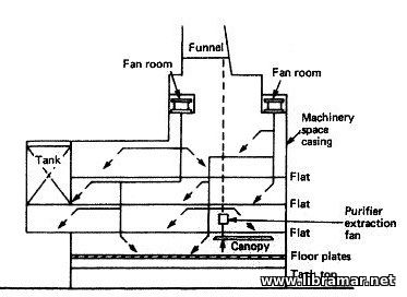 should be provided in the design of the system especially when ducts are placed above the ceiling. This will save considerable money and time when balancing the system. System balance is achieved by adjusting the position of the balancing dampers or changing orifice sizes such that the measured flow rates are within the tolerances noted. Care must be exercised in adjusting the flow in any one circuit since to do so will result in changing the flows in all other circuits of the system.
Construction Details
Ducts may be constructed of galvanized sheet steel in order to withstand corrosion and vibration, or ducts may be constructed of aluminum in order to save topside weight. If aluminum is used, special attention must be given to compliance with the U.S. Coast Guard fire-protection requirements. Built-in trunk construction may be used when the minimum dimension is 230 mm using adjacent bulkheads and similar structures for one or more sides. These trunks and all ducts exposed to the weather are built of not less than 32 mm plate and made watertight. Vertical and horizontal ducts in general cargo holds are usually constructed of 65 mm and 48 mm plates respectively.
Because of headroom requirements, most ducts are rectangular; round ducts being used only in the smaller sizes. Circular or oval ducts are used when passing through beams, girders, and other strength members. Usually a heavy section of ductwork is welded into the penetrated structure where structural compensation is required. Handholes, access holes, and portable sections are provided to permit cleaning, painting, and inspection.
Ducts passing over electrical equipment are made watertight. Flanged connections are provided for making all ducts portable, and flanged coamings are provided where ducts penetrate bulkheads, decks, and other structures. Ducts are made with either riveted, welded, or hook seams (Pittsburgh lock seams) and are airtight. Slip joints may be used for joining duct sections (they are especially useful in spiral wound duct installations), but good workmanship is essential to prevent leakage.
Galleys, bakeries, and food handling spaces present a special problem of heat, smoke, and odor removal. Mechanical exhaust is provided to exhaust the air from hoods over heat producing equipment. The mechanical supply should equal about 50 percent of the exhaust quantity. Supply air is discharged directly into the work areas. The remaining 50 percent is supplied by indraft from surrounding spaces. Supply air to the galley is usually preheated in winter and steam convectors or electric grids are often used for heating spaces such as toilets and lavatories.
To maintain habitable temperatures in machinery spaces and for the removal of fumes, spot cooling with large quantities of air at high terminal velocities, 13-15 m/s, is used at operating stations and other strategic locations. Exhaust terminals should be located in the vicinity of heat-producing equipment and on the upper levels of the machinery space. Occasionally, natural exhaust is used.
The exhaust air is discharged into the outer casing of the smokestack, the rest being utilized for forced draft blowers supplying it to the boilers of steam plants or to the intake air ducts of gas turbine and diesel plants for combustion. Generally, the supply air to machinery spaces is unheated and comfortable winter conditions are maintained by terminal volume dampers, two-speed fans, or by-pass ducts to admit outside air.
The "Read Later" function allows you to add material to this block with just one click. Just click on the icon and read the articles that interest you at any convenient time.