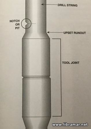
 Surface imperfections in the drill pipe metal greatly affect the fatigue limit of the metal. Imperfections can be mechanical or metallurgical. A notch or pit concentrates the stresses encountered during drilling and speeds the breakdown of the metal structure. They are, therefore, referred to as stress risers, or stress concentrators. Where the notch or pit appears on the drill pipe determines how much it will affect the fatigue limit of the pipe. If a notch is on a portion of drill pipe not subject to stress, the notch has little effect. If a notch is within twenty inches of a tool joint in the pipe’s upset runout, where maximum bending takes place, it can form the nucleus of an early fatigue break.
The shape and type of notch or scratch is also important. A longitudinal notch, an extensive saucer with a rounded bottom, will distribute the stress and be relatively harmless whereas a minute scratch with a sharp bottom will act as a stress riser and lead to failure.
Some steel is more sensitive to notches as other steel; notched brittle steel fails more quickly than ductile steel. Various surface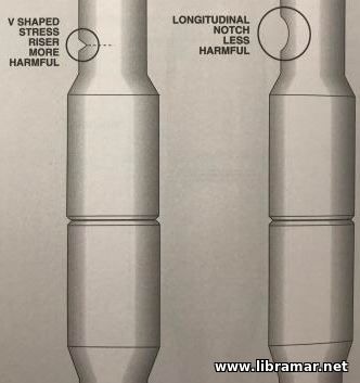 dents and scratches that can cause eventual drill pipe failure include the tong marks and slip marks, cuts, scratches, spinning chain marks and scratches, stencil markings, hammer marks, corrosion grooves caused by rubber protectors, electric arc burns, and downhole notching caused by formation and junk cuts. dents and scratches that can cause eventual drill pipe failure include the tong marks and slip marks, cuts, scratches, spinning chain marks and scratches, stencil markings, hammer marks, corrosion grooves caused by rubber protectors, electric arc burns, and downhole notching caused by formation and junk cuts.
Of all these defects, tong marks although rare, are probably the most damaging marks produced on drill pipe in the field. They are long, deep, and frequently sharped. Because such notches are longitudinal, they may not lead to notch failure. Even a slight deviation from vertical in the wellbore, however, can change the stress on the pipe and longitudinal notches can become stress concentrators. A change in the wellbore from vertical alters the stress along the defect from longitudinal to transverse. Tongs, therefore, should be applied to the tool joint, never to the body of the drill pipe, because the toll joint is thicker than is the pipe itself. In addition, applying tongs to drill pipe body may crush the pipe as well as notch it.
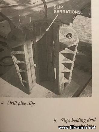
Rotary slips are made with fine serrations and are used to hold the pipe in place and to prevent it from slipping down into the hole when a connection is being made or broken out. The slips can, however, score the pipe if they are mistreated, worn, or carelessly handled. Slips with worn, mismatched, incorrectly sized, or improperly installed gripping elements can allow one or two teeth or portions of the teeth to catch the full load of the drill string, thereby causing deep notching and potential failure.
 Inasmuch as any transverse mark can be a dangerous stress concentration point, it is not surprising that steel stencil marks can be the start of fatigue when parts of the letter are transverse to the pipe and the steel stamp is in the wrong place. Never steel stencil on the drill pipe tube. Inasmuch as any transverse mark can be a dangerous stress concentration point, it is not surprising that steel stencil marks can be the start of fatigue when parts of the letter are transverse to the pipe and the steel stamp is in the wrong place. Never steel stencil on the drill pipe tube.
Corrosion at the top of the rubber pipe protectors can produce a circumferential groove. These grooves can lead to failure. Modern protectors are designed to minimize this risk. Because the protectors usually produce the grooves when they are left on the pipe while the pipe is in storage, the IADC recommends removing them before placing pipe in storage.
Welders sometimes attach the ground lead to the pipe rack instead of to the material being welded. This action is particularly dangerous in that the subsequent arcing between the rail and the drill pipe goes unnoticed. This arcing pits the pipe. Though these pits are small, they are surrounded by a wide band of burned metal that is as hard as glass and they are very prone to rapid fatigue failure.
It is very important that the drilling crew not run bent or crooked pipe into the hole. A crooked joint of pipe is always a potential failure. A crooked Kelly can cause bending in the first joint of drill pipe below the rotary table. If the stress is great enough, failure will occur. Having a crown block off center because the mast or derrick is not plumb can also cause pipe failure because the off-center block throws bending stresses into the Kelly and the drill string.
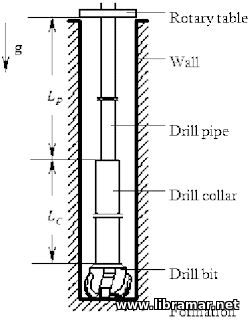 Unlike drill collars, the drill string is not ordinarily used to put weight on the bit. The drill string is made of steel or aluminum and is normally used for two basic purposes: to serve as a conduit, or conductor, for the drilling fluid; and to transmit the rotation of the rotary table or top drive to the bit on the bottom. Since it is not exclusively used to put weight on the bit, the drill string is smaller and lighter than the drill collars. In addition, in straight-hole drilling, it is suspended in the hole under tension, not compression. It is kept in tension by two opposing forces – the weight of the collars pulling it from the below and the hoist, line, and blocks pulling on it from the surface. Keeping the drill string in tension prevents it from bending and buckling and prolongs its life.
Manufacturers design the drill string so that it can withstand some of the most common stresses encountered during drilling. Relative to a drill collar, the drill string is small and thin, yet it can withstand powerful forces. Basically, the drill string is a column, or string, or drill pipe with attached tool joints. Most drill pipe is steel that is forged into a solid bar and then pierced to produce a seamless tube. Because the wall of the tube is relatively thin, usually less than half-inch thick, the manufacturer cannot cut threads into it. To solve the problem of providing threaded ends, so that the pipes can be screwed together, manufacturers produce tool joints.
The tool joint is a separate piece of metal welded onto a seamless drill pipe to produce the characteristic bulge at each end. The wall of the tool joint is thick enough to have the pin or the box cut into it. To prepare the drill pipe for welding, the manufacturer first heats the ends of the pipe and then strikes the heated end forcefully. These heavy end-on blows thicken the hot steel in the pipe ends. Manufacturers call the thickened ends “upsets”. The pipe maker thickens the last 3 to 6 inches of each end of the pipe to make it stronger.
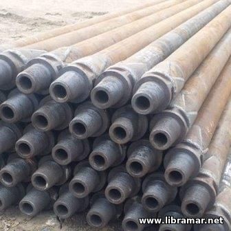 Each piece of drill pipe, excluding the tool joint, may have an outside diameter ranging from 2 3/8 to 6 5/8 inches (6.03 centimeters to 16.83 centimeters). Not only does the OD of drill pipe vary, but also the length of the pipe. Manufacturer make drill pipe in one of three API-recommended ranges of lengths. Range 1 lengths vary from 18 to 22 feet (5.49 to 6.71 meters). If a pipe measures, for example, 20 feet (6 meters) long, it would be range 1 length. Range 2 lengths fall within 27 to 30 feet (8.23 to 9.14 meters). Range 3 lengths are from 38 to 45 feet (11.58 to 13.72 meters).
Manufacturers produce these three ranges of lengths because derrick heights vary. The drilling contractor must be able to buy drill pipe lengths that make into stands of a height that fit inside the derrick. He drilling crew needs plenty of height above the stand to be able to manipulate it in the derrick. The most commonly used length of the drill pipe is the range 2 length. Most derricks are from 125 to 150 feet (38.1 to 45.2 meters) which allows a three-joint stand of 30-foot (about 9-meter) joints to fit into the derrick.
Manufacturers produce drill pipe according to API specifications concerning yield and tensile strengths. Minimum yield strength refers to the specific value at which the pipe will permanently distort. Minimum tensile strength refers to a specific value at which the pipe will snap, or pull apart. Drilling contractors determine what type drill pipe they need based on the conditions they expect to encounter downhole. The depth of the hole is the primary factor for determining what grade is needed. Other factors include whether or not the hole is straight or directional and the type of formations being drilled.
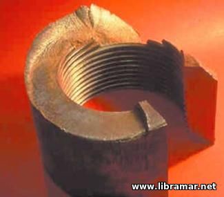 Corrosion is the alteration and degradation of material caused by its environment. Corrosion fatigue, or metal failure due to a corrosive environment, is a common cause of drill stem failures. With water-based drilling fluid, the chief corrosive agents of drill pipe are dissolved gases, such as the oxygen, carbon dioxide, and hydrogen sulfide, as well as dissolved salts, and acids.
Most modern drill pipe is made with a thermally baked plastic coating applied to the inner surface to minimize corrosion pitting. Wirelines and tools in the drill string bore tend to rupture or destroy the plastic coating that protects the pipe.
Among the many factors affecting corrosion rates of drill pipe are the following:
pH – it is a scale for measuring the hydrogen ion concentration of a particular environment. The pH scale is logarithmic; that is, each pH increment of 1.0 represents a tenfold change in hydrogen ion concentration. The pH of pure water is 7.0. pH values below 7 are increasingly acidic, and pH values greater than 7 are increasingly alkaline.in the presence of dissolved oxygen, the corrosion rate of steel n water is relatively constant between pH 4.5 and 9.5. The corrosion rate increases rapidly at lower pH values and decreases slowly at higher pH values. In drilling, the pH level rarely falls below 7. Most problems occur at pH levels between 7 and 10.5.
Temperature – in general, corrosion rates increase with increasing temperature.
Velocity – in general, corrosion rates increase with higher rates of fluid flow through the pipe.
Heterogeneity – in general, the more uniform the grain structure of a pipe, the less will be the corrosive effect of the environment. Localized variation in the composition of microstructure of the metal – that is, corrosion in small, well-defined areas – may increase the corrosion rates.
High stresses – highly stressed areas may corrode faster than areas of lower stress. The highest bending stresses occur in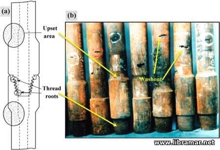 doglegs, where the tension is highest. doglegs, where the tension is highest.
Corrosion can take many forms and may combine with other destructive processes – erosion, abrasive wear, and notch failures – to cause severe damage. Several forms of corrosion may occur at the same time, but one type will usually predominate. The following forms of corrosion are most often encountered with drill pipe:
Uniform, or general attack – in this type of corrosion, the pipe corrodes evenly, usually leaving a coating a corrosion products, i.e. iron oxide, or rust;
Pitting, or localized, attack – in this type of corrosion, the pipe corrodes in small, well-defined areas, causing pits to form. These pits may vary in number, depth, and size; they may also be obscured by corrosion products. A drill stem inspection crew can detect pitting with magnetic inspection. Pits can serve as points of origin for fatigue cracks and lead to washouts. A washout is a place where a small opening has occurred in the pipe, usually as a result of a fatigue crack’s penetrating the pipe wall and allowing drilling fluid through it;
Corrosion fatigue – in a corrosive environment, no fatigue limit exists, since failure will ultimately occur from corrosion, even in the absence of cyclic stress. The cumulative effect of corrosion and cyclic stress is greater than the sum of the damage from each. The endurance limit, or fatigue threshold, will always be lower in a corrosive environment, even under mildly corrosive conditions that show little or no visible evidence of corrosion.
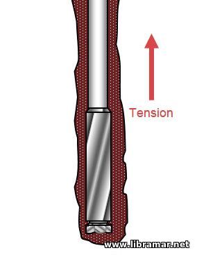 Even though the drill string is manufactured according to certain tested yield and tensile strengths, it is well known that the metal in the pipe is subjected to greater stresses under dynamic conditions in the well than under the static conditions of the lab. Steel has, however, the capability of absorbing cycles of stress for an infinite number of reversals if the stress is kept under a certain limit. This limit is referred to as the endurance of fatigue limit of the steel. If the stress never exceeds that point, any number of cycles will not cause the pipe to fail. It is difficult to measure precisely the fatigue limit of drill pipe because of the various stresses that can be encountered while drilling. It is, however, presumed to be approximately one-third to one-half the minimum tensile strength of the pipe.
Drilling beyond the fatigue or endurance limit will, depending on the number of cycles of stress, eventually cause the pipe to fail. To illustrate this point, consider bending a wire coat hanger back and forth with your hands. If you bend it only slightly, you can bend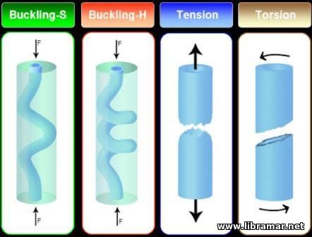 it forever without breaking the wire. Repeatedly bending it back and forth to a much greater degree will cause this wire to deform and eventually to break, however. it forever without breaking the wire. Repeatedly bending it back and forth to a much greater degree will cause this wire to deform and eventually to break, however.
The fatigue in any metal is progressive. Alternating stresses create heat in the section of the metal that is moving back and forth and reduce the strength of the metal. Submicroscopic cracks form that eventually unite until a crack becomes visible. The crack is normally perpendicular to the stress. Thus, drill pipe fatigue failures are circumferential or transverse – that I, they go around the pipe.
Rotating the drill string in a straight hole normally keeps the pipe well under the fatigue limit. But drill pipe is subjected to cyclical stresses of tension, compression, and torsion, particularly in doglegs and deviated holes. In fact, the major factor is fatigue-related failures in a hole that changes direction. Bending the pipe and rotating it at the same time in a curved hole submits the pipe to alternate cycles of bending or compression and tension. With each rotation, the side of the pipe that was under tension is put under compression and the side that was under compression is put under tension. Obviously, the greater the curve in the hole, the greater the levels of stress on the drill string.
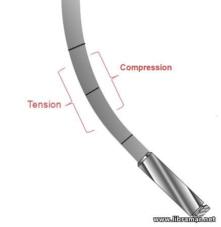 The maximum stress on the drill pipe occurs at the upset runout, that is, where the upset ends and the nominal wall of the pipe meet. The tool joint is strong so the most bending occurs in the relatively thin pipe wall. The maximum stress on the drill pipe occurs at the upset runout, that is, where the upset ends and the nominal wall of the pipe meet. The tool joint is strong so the most bending occurs in the relatively thin pipe wall.
The amount of fatigue damage to the pipe depends on several factors including, but not limited to the tensile load in the pipe at the dogleg, the severity of the dogleg, the number of cycles in each dogleg, the dimensions and properties of the pipe, and the corrodibility of the environment. A very corrosive drilling fluid will drastically shorten pipe life. The tensile load refers to the amount of tension, or pull on the pipe.
If drill pipe is damaged while rotating through a dogleg, the damage is permanent. Repetitive stresses accumulate and will eventually cause failure. Drill pipe may be damaged on one hole but not fail immediately. The failure can occur later and far from the position in the drill string when the trouble started, or the drill pipe may fail in subsequent wells.
In addition to the pipe’s failing as a result of metal fatigue, factors such as imperfections in the steel and bend pipe can increase the likelihood of failure.
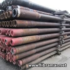 Drill collars are heavy and award to move around the rig. The crew must be very careful to prevent damage to the threaded ends and shoulders. Putting the heavy collars down on unprotected threads or knocking the threads with another collar can easily damage them. Crew members should keep thread protectors on both ends of the collar when they move the collars around the rack and across the catwalk. Some thread protectors have bails, or handles, which make it easier for crew members to pick up the collar. Regardless of how collars are moved, the thread protectors should be in place first.
When crew members are ready to move the collars through the V-door, they use a lifting sub or nipple screwed onto the collars if the collars do not have recesses. Unless manufactured with recesses, collars require either subs or nipples to provide a place for the elevators to attach. Before using subs or nipples, however, crew members should check the threads and the shoulder on the subs or nipples to be sure they are clean and that they fit the collar.
Before a drill collar can be made up to another one, crew members should make sure that the threads are clean and dry and that they are not rusted. Keeping the threads clean increases the life of the connections by eliminating any abrasive materials that can damage the threads. Crew members should also inspect the collar to make sure that it is not damaged. A damaged drill collar should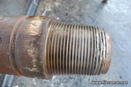 never be run into the hole. The drilling crew should regularly inspect the collars to make sure they are in good condition. Even slight damage can cause problems downhole. never be run into the hole. The drilling crew should regularly inspect the collars to make sure they are in good condition. Even slight damage can cause problems downhole.
After crew members have made sure that a collar is clean and in good condition, they can make it up to the bit or to another collar. They should apply a good coating of thread compound, or dope, to the threads and shoulders. This lubricant, normally a soft metallic component like copper or zinc in a grease base, lubricates and separates mating threads and shoulders in spite of the high stresses put on them during makeup and while drilling. It also makes it easier to screw the two joints of collar together. Crew members should never dilute or thin the thread component because this will reduce the percentage of metallic component and thus increase the chances of galling the threads. Because many cleaning fluids used on the collars can dilute the lubricant, crew members should make sure that the collar threads are completely dry before applying the compound.
The crew should take great care not to damage the threads or shoulder when stabbing the pin into the box. Dropping the pin onto the box shoulder or jarring the threads during makeup can cause severe damage.
After stabbing the pin of one collar into the box of another, crew members hand-tighten the two collars together by ”walking in” the one on top while the rotary keeps the lower one stationary. Hand-tightening the collars before making them up to final torque helps preserve the threads. The crew should hand-tighten the collars using the chain torques rather than the spinning chain because the spinning chain would spin too fast and possibly gall the threads. Also, the collars are so big and heavy that it is easier for the crew to hand-tighten them by holding the top collar with tongs and walking around the rotary turning the top collar until it is screwed into the bottom collar. On some rigs the crew uses a spinning wrench to make up the collars hand-tight. The crew can use the spinning wrench only on collars that are not over 9 1/8 inches in diameter. If the outside diameter of the collar is larger than that, the wrench will not fit around it.
To make up the drill collars to the final recommended torque, the crew uses the breakout tongues and the cathead. The drill collars are so heavy that they require a great deal of pulling force to be made up to proper tongue. The breakout cathead uses a very strong cable attached to the end of the breakout tongs. Cable is stronger than chain and is therefore less likely to break. In addition, the breakout cathead and cable are located well away from the driller. Thus, if there is a break in the cable, the driller will not be in danger. If crew members used the makeup cathead and tongs, they would be using a chain instead of a cable and would be much closer to the driller – too close for safety. Drill collar connections should never be made up or broken out by turning the rotary because the rotary spins the collars with too much force and the collars can be damaged. After crew members have broken a connection using the tongs, they may then use the rotary to finish spinning it out.
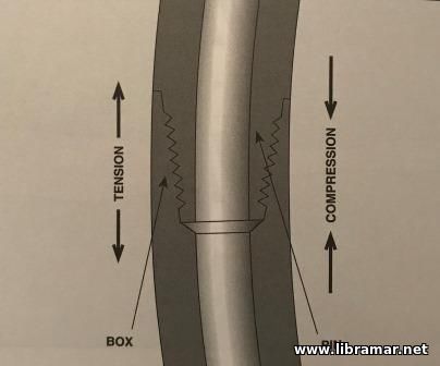 Although drill collars are heavy and stiff, they can fail. A single drill collar on the rack may appear to be so heavy and stiff that it cannot bend, but when three of the collars are screwed together and standing in the derrick, a definite bend is noticeable. In the hole, twenty of these collars may be stacked into a long and relatively limber column that bends when compressed by the weight of the entire column. During drilling, rotational force puts even more stress on the collars. In fact, the tension and compression put on collars during drilling can result in cracks and bends.
In any string of drill collars, the metal fibers on the outer side of a bend are under tension while on the inner side of a bend are under compression. If the collars are rotated one-half turn, the fibers that were under tension are put under compression. In every drill collar rotated in the hole. This continuous movement from tension to compression takes place with each rotation of the drill stem.
In a drill collar, there are two main areas of stress concentration – one in the pin, and one in the box. Drill collars usually fail in the threaded connections because most of the bending stress is concentrated at that point. If the surface of any drill stem component is cracked, the crack tends to enlarge every time it comes to the tension side of the bend. Such cracks are called fatigue cracks.
Making a Good Connection
In order to reduce the number of drill collar failures, crew members should make up a drill collar joint correctly – that is, they should make a good connection. They should use a proper torque (the proper amount of turning force needed to screw the two collars together), proper procedures, and the correct amount of lubricant, also called thread compound, or dope. In a good connection, the shoulders of the collar support the pin so that it is rigidly held by the box.
In a good connection the only seal between the two joints is made between the shoulders of the pin and the box. The pin and the box serve as a simple screw jack pulling the two shoulders together very tightly. Unlike the threads in tubing and casing, which produce a continuous seal, the threads of the collars do not form a pressure seal. In a good connection, the shoulders on the collars must be connected with adequate preload, or proper makeup torque, to produce a seal that will hold even under the tension and compression put on the drill collars during drilling.
Failures with Good Connections
Even when the crew makes up the drill collars correctly, the drill collars can sometimes fail. The weakest section in a good connection may be the narrow cross section in the bottom of the badly worn box, or a box with low bending strength near the end of the pin. As mentioned earlier, the bending strength of the box should be 2 ½ times greater than the bending strength of the pin to withstand the stresses during drilling. During drilling, rotation of the drill collars puts high cyclic stress on the bottom of the box. A 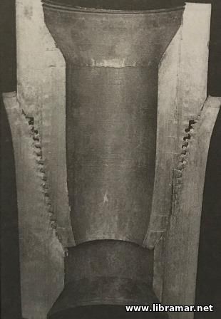 small crack may form, which can result in a box failure. small crack may form, which can result in a box failure.
Making a Bad Connection
A crew can make a bad connection by using too little torque, too much torque, an inadequate amount of the proper lubricant, or improper procedures. When crew members use too little torque, tension in drilling can cause an opening between the shoulders of the pin and the box. As the drill collar above the shoulders bends to one side, it puts a severe tension load on one side of the collars and compression on the other. As the drill collar rotates one-half turn, the side that was in compression, is now in tension; the sie that was in compression, is now in tension. If the collars were not made up to the proper torque, this rocking back and forth may cause a leak between the shoulders. Every time the seal breaks, drilling fluid passes across the shoulder.
If drilling fluid passes across the shoulder, the lubricant, or dope, between the shoulders washes out, and the surface of the shoulders begins to erode. In addition, if enough fluid moves through the seal, the lubricant is washed away from the threads as well as from the shoulders. The crew can recognize a loose joint when breaking out drill collars because the pin is dry.
Failures with Bad Connections
When drilling with an undertorqued connection, failures normally occur in the first or second thread near the base of the pin; this thread is often referred to as the last engaged thread, or LET. Occasionally, however, the box fails – not at the bottom, but 1 ½ to 2 inches from the shoulder at about the third or fourth thread. Such failures occur when the box cross sections are relatively weak compared to the pin.
Too little torque causes more failures than too much torque, but too much torque, especially with smaller-sized collars, may result in failures also. Failures caused by overtorquing occur in the weaker member – in the LET near the base of the pin or in the box is the shoulder is small. If the crew makes up the pin and the box together with too much torque, something will break. The tongs break, the pulling line breaks, or the box swells as the overtorqued pin pushes against it. The pin may actually screw through the box. Sufficient torque must be used to make a good connection, but too much torque causes failure.
The shoulder area can be too small to form a good connection because the pin or box has been improperly machined o because the outside diameter of the box has been severely worn. In either case, the box shoulder cannot support the bending stresses 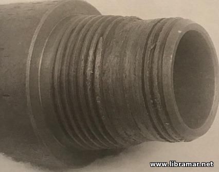 imposed on it by the pin because it has a small contact area. This means that the connection cannot long withstand the forces placed on it during drilling. The high bending stresses on the box near the mouth cause the shoulder to shear off and the box to bell and swallow the pin. imposed on it by the pin because it has a small contact area. This means that the connection cannot long withstand the forces placed on it during drilling. The high bending stresses on the box near the mouth cause the shoulder to shear off and the box to bell and swallow the pin.
When rotating downhole, drill collars tend to overtighten when drilling torques are high – that is, they tend to screw together even more tightly than when they were made up. The result may be a belled box. Slick thread components aggravate this problem by allowing the connection to be overtorqued more easily. Box failures of this type are rare if the joint has a good balance between pin size and the outside diameter of the box. If drill collars with narrow shoulders must be used, the driller should make sure the joints are made up to the proper torque, avoid high torques while drilling, and use a high-quality drill collar thread lubricant.
High stress loads on mating threads and shoulders and inadequate or improperly applied thread compounds may lead to galling. Galling occurs when two mating steel surfaces, such as metallic zinc or copper, not protected by a film of lubricant, the metal is torn apart and the threads and shoulders are damaged. Galling at its worst can destroy one or both makeup shoulders and can wipe out all the threads in a pin or a box. Galling is more frequent on newly machined surfaces.
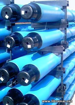 Let us shed some light on the important functions of the string of drill collars.
Weight on Bit
As discussed earlier, drill collars provide weight on the bit in order to make the bit gouge into the earth and make hole. The amount of weight required depends on several factors. The well planner considers the kind of formations being drilled, the diameter of the hole, the kind of bit being used to drill, the buoyant effect of the drilling fluid, the tendency of the hole to deviate from a true vertical path, and other variables. The correct amount of weight on the bit helps make for efficient drilling of the hole. The weight of each drill collar depends on the OD and the ID, or bore, of the pipe. The weight or force needed on the bit will significantly differ depending on the diameter of the hole.
The buoyant effect of the drilling fluid in the hole must be taken into consideration when determining WOB. Just as a boat floats 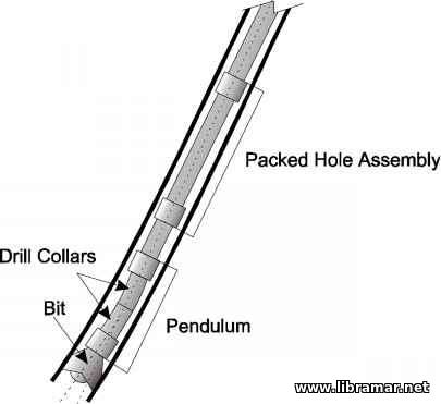 on water, the drill stem floats in drilling fluid, thereby reducing the amount of weight on the bit. The denser the drilling fluid, the greater the buoyant effect, so more drill collars are needed to provide the same weight on the bit. Drilling crews often use additional collars to offset this buoyancy. To account for the buoyant effect of the drilling fluid, the operator takes the required WOB and divides it by the buoyancy factor of the mud to arrive at the air weight of the drill collars. on water, the drill stem floats in drilling fluid, thereby reducing the amount of weight on the bit. The denser the drilling fluid, the greater the buoyant effect, so more drill collars are needed to provide the same weight on the bit. Drilling crews often use additional collars to offset this buoyancy. To account for the buoyant effect of the drilling fluid, the operator takes the required WOB and divides it by the buoyancy factor of the mud to arrive at the air weight of the drill collars.
The amount of deviation in the wellbore must also be taken into consideration when determining WOB. The more the hole deviates from vertical, the greater is the reduction in effective WOB. So, depending on how much the hole deviates from vertical, the well planner must increase the number of drill collars to provide the required WOB.
Holding the Drill String Straight
In addition to putting weight on the bit to make hole efficiently, drilling crews must also use the weight of the collars to keep the drill string above the collars from bending or buckling. If the drill string is kept in tension, it will not bend or buckle. The drill string is kept in tension by two opposing forces – the weight of the drill collars pulling it from below and the drawworks and drilling line pulling it from the surface.
Under normal condition, the drill pipe string wears more rapidly near the center of each joint. Bending or buckling increases the metal fatigue in the center of the joint – that is, bending increases the stress factors in the pipe’s weakest area. Bending also forces the drill string to rub against the wall of the hole, which abrades the sides of the pipe.
Sometimes the driller uses extra weight on the collars to make sure that the drill string stays straight. When using additional weights to hold the drill string straight, the driller usually uses drill collars having a buoyed weight 10% to 30% greater than the amount needed to just to make hole. Providing this extra weight will help keep the string relatively straight as it is rotated.
Providing a Pendulum Effect
Drill collar weight also provides a pendulum effect to cause the bit a drill a more nearly vertical hole. In straight-hole drilling, the most efficient drilling is that which produces a nearly vertical path to the target. Any deviation from vertical tends to increase the cost of the well. Of course, no hole is absolutely vertical from the surface to completion. Different causes force the hole to deviate from 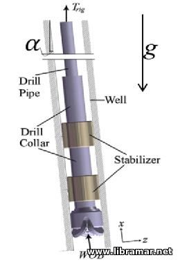 vertical. The job of the drilling crew is to keep the wellbore as vertical as possible. vertical. The job of the drilling crew is to keep the wellbore as vertical as possible.
As stated previously, one phenomenon that assists the driller in straight-hole drilling is the pendulum effect. The pendulum effect is the tendency of the drill stem to hang in a vertical position because of the force of gravity pulling on the drill collars. The heavier the pendulum, the stronger is its tendency to remain vertical and the greater is the force needed to cause the drill stem to deviate from vertical. If the drill stem deviates from a true vertical path, the force of gravity tends to pull it back toward vertical. The bit and drill collars tend to drill on the low side of the hole as they seek a more nearly vertical path.
The length of the pendulum is that section of the drill collar string between the bit and the lowest-point tangent to the side of the hole. The lowest-point tangent to the side of the hole is the point at which the drill collars first touch the sides of the hole or at which the first stabilizer touches the sides of the hole. The drilling crew tries to keep this point as high as practical so that the pendulum will be as long as possible. The longer the pendulum, the greater is the tendency for the drill stem to seek a vertical position. There is a limit, however, on the spacing between the bit and the first stabilizer. If the distance is too great, the drill collars may buckle. Tables are available to assist in selecting the appropriate spacing in relation to hole size, drill collar OD and ID, and the angle of the hole.
The weight, the length, and the stiffness of the pendulum are important in straight-hole drilling. A stiff drill collar assembly has a higher point of tangency than a limber one. To achieve both weight and stiffness, crew use large, heavy collars. Undersized and relatively limber drill collars, with a large clearance between the OD of the collar and the wall of the hole, make it harder to keep the hole vertical. Relatively limber drill collar strings tend to bend or flex near the bit; this bending shortens the pendulum considerably 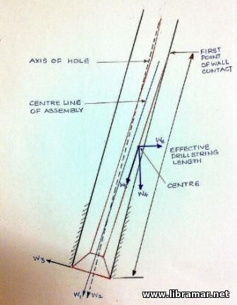 and increases the deviation from vertical. and increases the deviation from vertical.
Stabilizing the Bit
Drilling crews use large, heavy, round drill collars with stabilizers to help stabilize the bit when drilling. They use these collars and stabilizers to create what is called a packed bottomhole assembly, or BHA. This term refers to the fact that round drill collars with stabilizers in the lower part of the drill collar assembly are almost the same OD as the bit. In addition, the stabilizers are no more than 1/8 inch smaller in diameter than the hole. In a packed BHA composed of a bit and round drill collars with three or more stabilizers above it, the crew places the first stabilizer immediately above the bit, followed by a short, large-diameter drill collar and a second stabilizer. The third stabilizer is located farther up in the drill collar string.
The use of a packed bottomhole assembly is sometimes referred to as a gun-barrel approach because when the crew uses this assembly, the bit tends to drill straight ahead in spite of forces trying to prevent it from doing so. In other words, the assembly assures that the new wellbore is being drilled in line with the hole that has already been drilled; it is as straight as the barrel of a gun. Using a packed BHA, or the gun-barrel approach, keeps the bit from wobbling, or walking, on the bottom of the hole. This approach also keeps the pressure on the cutting structure of the bit uniform, thereby forcing the bit to cut evenly through the formation. A bit that is not connected to a packed bottomhole assembly may drill an oversize hole, produce unusual bit wear, and slow the rate of penetration. In general, bits drill faster and last longer when well stabilized.
|

 dents and scratches that can cause eventual drill pipe failure include the tong marks and slip marks, cuts, scratches, spinning chain marks and scratches, stencil markings, hammer marks, corrosion grooves caused by rubber protectors, electric arc burns, and downhole notching caused by formation and junk cuts.
 Inasmuch as any transverse mark can be a dangerous stress concentration point, it is not surprising that steel stencil marks can be the start of fatigue when parts of the letter are transverse to the pipe and the steel stamp is in the wrong place. Never steel stencil on the drill pipe tube.


 doglegs, where the tension is highest.
 it forever without breaking the wire. Repeatedly bending it back and forth to a much greater degree will cause this wire to deform and eventually to break, however.
 The maximum stress on the drill pipe occurs at the upset runout, that is, where the upset ends and the nominal wall of the pipe meet. The tool joint is strong so the most bending occurs in the relatively thin pipe wall.
 never be run into the hole. The drilling crew should regularly inspect the collars to make sure they are in good condition. Even slight damage can cause problems downhole.
 small crack may form, which can result in a box failure.
 imposed on it by the pin because it has a small contact area. This means that the connection cannot long withstand the forces placed on it during drilling. The high bending stresses on the box near the mouth cause the shoulder to shear off and the box to bell and swallow the pin.
 on water, the drill stem floats in drilling fluid, thereby reducing the amount of weight on the bit. The denser the drilling fluid, the greater the buoyant effect, so more drill collars are needed to provide the same weight on the bit. Drilling crews often use additional collars to offset this buoyancy. To account for the buoyant effect of the drilling fluid, the operator takes the required WOB and divides it by the buoyancy factor of the mud to arrive at the air weight of the drill collars.
  vertical. The job of the drilling crew is to keep the wellbore as vertical as possible.
 and increases the deviation from vertical.