 Tankers transport some of the most dangerous flammable cargo that is carried at sea. Yet, what was the last time you have heard of one actually exploding? Sure, you do hear of tankers that have suffered fires and explosion; we also had numerous tankers damaged I the Gulf and other areas. Yes, none of them have truly exploded. We are talking about the sort of explosions we ae seeing with rockets and cars that have been engulfed in flames. In these explosions there is always nothing left. This has happened with ships in the past. In 1976, the tanker “Santa Nina” exploded in Los Angeles. The resultant shockwave literally blew the ship apart and it shattered windows on houses over twenty miles away.
How then do modern tankers carrying thousands of tons of flammable fuel not just exploded in the same way the “Santa Nina” did? To answer that, we need to know a little behind the science of burning hydrocarbons. We all know that burning is just a process of a fuel reacting with oxygen and giving off heat. Obviously, in our case the fuel source we are talking about is the cargo that is carried and the oxygen is in the air. Let’s assume we are just carrying a random hydrocarbon fuel in the tank and it is a liquid at atmospheric pressures and temperatures. The liquid itself does not burn; that is kind of obvious if we think about it. There is no oxygen within the liquid itself – it is only actually the vapors that burn. As fuel evaporates off the surface, it mixes with the oxygen in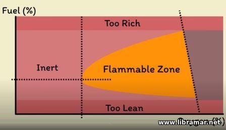 the air and then it just takes a heat source to ignite. The exact proportion of fuel vapor to air needed to catch light does vary, but we can represent that on a flammability diagram. the air and then it just takes a heat source to ignite. The exact proportion of fuel vapor to air needed to catch light does vary, but we can represent that on a flammability diagram.
There, you can see the percentage of hydrocarbon gas represented on a vertical line and along the bottom we have the percentage of oxygen. If you only have tiny amount of hydrocarbon gas in the air, clearly it is not going to ignite. We say the mixture is too lean; likewise, if you have too much hydrocarbon gas, we say it is too rich. We are left with the area somewhere in the middle of the diagram. So, next we come to the oxygen content. Obviously, normal air has around 21% oxygen, so there is no point going above that because we are not pumping extra oxygen in. you see the dashed line actually sloping a little – that is because the oxygen percentage will naturally decrease when you start mixing in fuel particles.
Finally, at the lower end we have the part of the graph representing a low oxygen level. If the oxygen level is too low, again it is clear that the mixture is not going to ignite. We say the mixture is inert – you do reach a point where the oxygen percentage is just right. If you have the perfect percentage of fuel, then as the oxygen level increases, the range at which the fuel could burn expands. Within the subject area we have the flammable one. If the proportions fall within it, a heat source will ignite the mixture. So, how can we control that?
In a way, the percentage of hydrocarbon is out of our control. It naturally evaporates from the surface of the fuel, so the concentration will vary throughout the tank. The only way we can prevent ignition is to lower the percentage of the oxygen close to the fuel so that it becomes inert. You basically need to add the inert gas – helium, nitrogen, argon, compounds like carbon dioxide – just something will not allow the fuel to burn. Obviously, there are cost implications for the noble gases, so argon and helium are not really a commercially viable option, and leave us with the nitrogen and carbon dioxide option. If you want to go into the expense of generating the gas and containing it, you will probably use nitrogen, as it is in the high percentage in the atmosphere anyway, so it is going to have minimal impact on the cargo in terms of contamination.
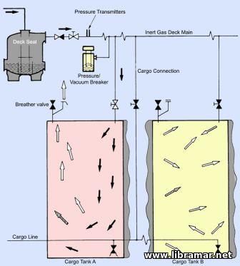 If contamination is not a concern, you can use carbon dioxide and the massive advantage of carbon dioxide is that the ships have carbon dioxide generator already - the main engine producing it as a byproduct of combustion of its own fuel. All we need to do is to clean up the exhaust and we can do that with the inert gas plant. We first pass the flue gas through a scrubbing tower and that cools it down and removes solid contaminants. We then send it through powerful fans that can maintain the same pressure as the cargo tanks – this is to prevent the tanks from buckling if you are emptying them too quick, much like a bottle of water you squeeze to hard. As it crosses the safety barrier into the cargo area, it then passes through some sort of a non-return valve. Commonly, this is a water seal the inert gas can happily bubble through and flow to the tanks, but if flammable vapor from the tanks tries to come out, it creates a water plug, which blocks return to the rest of the ship. If contamination is not a concern, you can use carbon dioxide and the massive advantage of carbon dioxide is that the ships have carbon dioxide generator already - the main engine producing it as a byproduct of combustion of its own fuel. All we need to do is to clean up the exhaust and we can do that with the inert gas plant. We first pass the flue gas through a scrubbing tower and that cools it down and removes solid contaminants. We then send it through powerful fans that can maintain the same pressure as the cargo tanks – this is to prevent the tanks from buckling if you are emptying them too quick, much like a bottle of water you squeeze to hard. As it crosses the safety barrier into the cargo area, it then passes through some sort of a non-return valve. Commonly, this is a water seal the inert gas can happily bubble through and flow to the tanks, but if flammable vapor from the tanks tries to come out, it creates a water plug, which blocks return to the rest of the ship.
Of course, the system itself is somewhat more complicated than this; we have numerous isolation valves, PV breakers and temperature protection systems. Overall, the system allows us to put the engine exhaust through the cargo tanks, lowering the percentage of oxygen. This plays back into that flammability diagram, bringing the tank atmosphere safely down into the inert area. It is no longer possible for the flammable cargo vapors to ignite and this is why fires and explosions on modern tankers do not result in the same catastrophe that was witnessed in Los Angeles.
 Many different types of pumps exist to assist fluid movement in a variety of systems.
External Gear Pump
An external gear pump uses two gears rotating against each other to provide fluid movement. One gear is driven by a motor connected to a shaft – this is called a drive gear because it is driven by a motor and it in turn meshes with and drives the movement of the second gear. As the gears rotate away from each other and come out of mesh, they create an expanding volume on the inlet 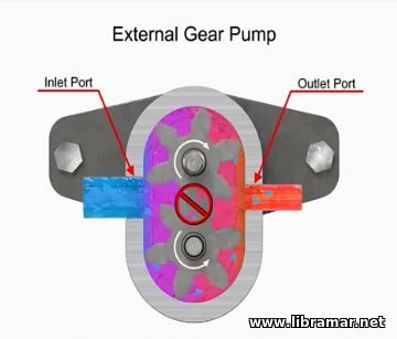 side of the pump. side of the pump.
This creates vacuum at the inlet port, allowing fluid to flow into the pump. Then, fluid flows into the cavities and is trapped by the gear teeth. As the gears rotate, a flow path is created around the outside of each one. Fluid trapped in the slots between the teeth is carried around and discharged into the cavity with the outlet port. Meshing of the teeth in the center of the pump seals the outlet port from the inlet port – no fluid passes between the gears.
at their design accommodates wide variety of materials. Disadvantages include bushings in the liquid area can become worn and that they have fixed end clearances.
Internal Gear Pump
Internal gear pumps are exceptionally versatile. This type of pump has one inner gear which is inside a second, outer, gear. The inner gear has a shaft driven by a motor and has teeth that protrude outward. The outer gear has the teeth that protrude inward 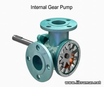 toward the center of the pump. As the inner gear rotates, it meshes with and moves the outer gear. Liquid is trapped in the gear spaces and carried from inlet to the discharge. A stationary crescent-shaped divider separates the intake and discharge portions of the fluid. toward the center of the pump. As the inner gear rotates, it meshes with and moves the outer gear. Liquid is trapped in the gear spaces and carried from inlet to the discharge. A stationary crescent-shaped divider separates the intake and discharge portions of the fluid.
Advantages of internal gear pumps are their smooth and almost pulseless flow, and slightly more horse power for the size. Disadvantages are their cost, limited size range, low to moderate pressure ratings, and few sources of manufacture.
Rotary Vane Pump
A rotary vane pump is a positive displacement pump that consists of vanes, mounted to a rotor. The vanes are on a off-center drive shaft. As the shaft rotates, the 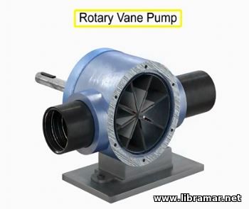 variable-length vanes slide in and out to maintain contact with the pump housing. The tension in the vanes is maintained by either springs or hydraulic pressure. As the vanes rotate, they create chambers of varying sizes within the pump. Fluid enters at the largest chamber. As the vanes rotate and retract, the chambers get smaller, forcing fluid to exit through the discharge port. variable-length vanes slide in and out to maintain contact with the pump housing. The tension in the vanes is maintained by either springs or hydraulic pressure. As the vanes rotate, they create chambers of varying sizes within the pump. Fluid enters at the largest chamber. As the vanes rotate and retract, the chambers get smaller, forcing fluid to exit through the discharge port.
The advantages of vane pumps are that they can handle low viscosity fluids at relatively high pressures, can dry run for short periods, and develop a good vacuum. Their disadvantages include complexity and unsuitability for both high pressure and high viscosity fluids.
Piston Pumps
Piston pumps come in many different forms. A swash plate is a device used to translate the motion of the rotating shaft into 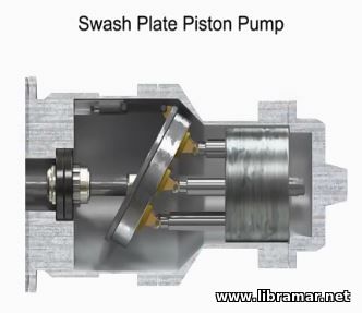 which are pressed against the stationary swash plate that sits at an angle to the cylinder. As the shaft rotates, the pistons move against the swash plate, causing them to reciprocate within the piston block. The pistons create a vacuum that forces fluid in during half a revolution, and expels during the other half. which are pressed against the stationary swash plate that sits at an angle to the cylinder. As the shaft rotates, the pistons move against the swash plate, causing them to reciprocate within the piston block. The pistons create a vacuum that forces fluid in during half a revolution, and expels during the other half.
On the intake stroke a spring ensures the pistons is pulled back and maintains contact with the swash plate causing fluid to fill in the empty cavity left behind. On the discharge stroke the angle of the swash plate forces the pistons back inside the piston block and discharge the fluid. Piston pumps in general are manufacturer with closer internal fits than other pumps; this means that internal slippage can be less so that they operate within reasonable efficiency at pressures both too high and too low for the operation of other pumps.
Radial Pumps
Radial pumps are designed so the piston stroke in a direction at right angles to the shaft. The pistons are arranged like wheel spokes around the cylinder block with the eccentric cam mounted on a drive shaft. As the shaft rotates, the cam moves toward the pistons forcing them down into the cylinder block and discharging the fluid. As the cam moves away, springs help retract the piston and cause the intake stroke. Check valves ensure that fluid only enters the inlet ports and only exits the outlet ports. Radial piston pumps have a low noise level, very high loads at low speeds, and high  efficiency. efficiency.
Hand Pumps
Hand pumps are used when a source of power is not available or where the extra expense of a power pump is unwarranted. They are always of piston type and are usually constructed with a piston working between two check valves. Double acting hand pumps are more efficient, allowing fluid to both enter and discharge on both strokes of the piston. Moving the pump handle in any direction allows fluid to be drawn in from the reservoir and discharged via the outlet ports. Check valves in all locations prevent fluid backflow.
 Rudder evolved from steering board that was used in ancient times. Steering board was usually mounted on the right-hand side to suit right-handed sailors. In time, the steering board moved to a centerline through a stock passing though the vessel. A tiller was then attached to the stock allowing sailors to control the rudder from the main deck.
The basic setup continued right up to the modern times. You can still see the modern rudders carrying same characteristics as the original steering board. It is a small flat board mounted on a stock passing through the ship. Let us have a look on how it works.
Here we have a simple hull and I am just going to attach a normal rudder to the stern. If we keep a rudder amidships, we can 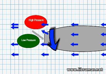 watch how the water flows around the hull-rudder combination. It flows evenly and this means there is not turning force generated. So, the hull should move in a straight line. If we now turn the rudder to port, we can see the effect it has on the flow of water. This board type rudder has now directed the water in a different direction. The water is being directed at an angle away from the boat. The extra water increases the pressure exerted on one side and decreases the pressure on the other side. This pressure difference pushes the stern in the direction shown by the arrow, inducing the desired turn to port. As a speed of the water increases, effectiveness of the rudder also increases. This why the rudder appears more sensitive at higher speeds. watch how the water flows around the hull-rudder combination. It flows evenly and this means there is not turning force generated. So, the hull should move in a straight line. If we now turn the rudder to port, we can see the effect it has on the flow of water. This board type rudder has now directed the water in a different direction. The water is being directed at an angle away from the boat. The extra water increases the pressure exerted on one side and decreases the pressure on the other side. This pressure difference pushes the stern in the direction shown by the arrow, inducing the desired turn to port. As a speed of the water increases, effectiveness of the rudder also increases. This why the rudder appears more sensitive at higher speeds.
But what if we now change the shape of the rudder slightly? We could make it resemble the wing of an aircraft. Aircraft wings generate lift by forcing air to flow quicker across the curve top surface of the wing. This kind of sucks aircraft into the air and this is far more efficient that just using a flat wing at an angle. If we apply this 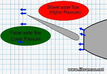 principle to a rudder, it gives us a new shape shown on the picture. We will call this the airfoil shape. Again, when the rudder is amidships, there is no deflection in water flow so the boat remains in a straight line. If we turn the rudder, again the water will be deflected off to one side. This time, however, the shape of rudder forces water to run over curved path. The water on one side will have to flow faster to flow around the rudder. Water on the other side, conversely, has to flow slightly slower. This speed variation adds to the pressure difference generated by deflection alone that we saw before. The side shown in red is actually higher pressure than it was for a flat rudder; likewise, the side shown in green is even lower pressure than it was before. All it means is that for a given speed of water the curved airfoil shape rudder will turn about more efficiently than a flat rudder. principle to a rudder, it gives us a new shape shown on the picture. We will call this the airfoil shape. Again, when the rudder is amidships, there is no deflection in water flow so the boat remains in a straight line. If we turn the rudder, again the water will be deflected off to one side. This time, however, the shape of rudder forces water to run over curved path. The water on one side will have to flow faster to flow around the rudder. Water on the other side, conversely, has to flow slightly slower. This speed variation adds to the pressure difference generated by deflection alone that we saw before. The side shown in red is actually higher pressure than it was for a flat rudder; likewise, the side shown in green is even lower pressure than it was before. All it means is that for a given speed of water the curved airfoil shape rudder will turn about more efficiently than a flat rudder.
Let us now we modify the shape further by adding an additional flare at the end. We call this a fishtail, or a Schilling rudder – 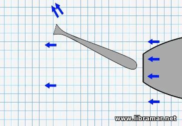 such arrangements is in use on many ships due to the increased maneuverability at slower speeds. Again, the water flows evenly around the rudder when it is amidships. This time, when we turn the rudder, we can see the additional water deflection. We have the same initial deflection as we did with the board rudder, we have the flow speed differential we did with airfoil, and now we have the additional deflection created by the flare at the very tail of the rudder. This reduced that wasted water flow that was previously flowing around the edge of the training edge. This combination acts to further increase the efficiency of the rudder. If it is more effective at the same speed, the logical deduction is a less water flow to generate the same turning effect. These rudders are more effective at slow speeds, making them particularly useful for slow ship handling. such arrangements is in use on many ships due to the increased maneuverability at slower speeds. Again, the water flows evenly around the rudder when it is amidships. This time, when we turn the rudder, we can see the additional water deflection. We have the same initial deflection as we did with the board rudder, we have the flow speed differential we did with airfoil, and now we have the additional deflection created by the flare at the very tail of the rudder. This reduced that wasted water flow that was previously flowing around the edge of the training edge. This combination acts to further increase the efficiency of the rudder. If it is more effective at the same speed, the logical deduction is a less water flow to generate the same turning effect. These rudders are more effective at slow speeds, making them particularly useful for slow ship handling.
The final type of rudder we are going to look at is an active rudder. If we go back to the airfoil shape, at this time we are going to break it near the tip, the tip can then be linked to the main body of the rudder by mechanical linkage that forces it to turn further that the main rudder. For example, if you turn the rudder to ten degrees, the mechanical linkage will turn the turn the tip of further ten 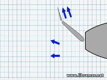 degrees. This applies throughout the whole range of movement of the rudder; at 35 degrees the tip will be 35 degrees further, which is 70 degrees from the direction of movement. We call this type of rudder the flap rudder or Becker rudder. Becker is the name of the man and the company that developed the rudder, so it is actually just a brand. When we look at the water flow diagram for a flap rudder, we can see again that amidships there is no turning force generated. When we turn the rudder, we have the same change in the water flow as before, much like Schilling rudder, the flap rudder generates that additional increase at the tip. This time, however, the increase at the tip continues to increase even further the further you turn the rudder. When the rudder is hard over, the tip is practically directing water sideways. This makes a flap rudder one of the best options for very slow ship handling. This rudder is very effective at slow speeds. degrees. This applies throughout the whole range of movement of the rudder; at 35 degrees the tip will be 35 degrees further, which is 70 degrees from the direction of movement. We call this type of rudder the flap rudder or Becker rudder. Becker is the name of the man and the company that developed the rudder, so it is actually just a brand. When we look at the water flow diagram for a flap rudder, we can see again that amidships there is no turning force generated. When we turn the rudder, we have the same change in the water flow as before, much like Schilling rudder, the flap rudder generates that additional increase at the tip. This time, however, the increase at the tip continues to increase even further the further you turn the rudder. When the rudder is hard over, the tip is practically directing water sideways. This makes a flap rudder one of the best options for very slow ship handling. This rudder is very effective at slow speeds.
With all of the rudders we have looked at, you see that water flow is needed for them to work at all. On a sailing boat, boat needs to be moving for a rudder to have any effect. On a motorboat or on the ships that are powered by engines, you have got two options – either you need to be moving through the water, or the propeller needs to be turning, pushing water across the rudder. Another thing to think about with rudders is that you do not want them to stall in the same way that if an aircraft points up too charply they will stall, if you turn the rudder too far, it is going to stall.
 General Description and Definition
Air conditioning systems serve to modify the outside fresh air to improve the ship's interior environment. This is accomplished by heating, cooling, dehumidifying, and contaminant removal processes. These processes may be used singularly or in combination to achieve the required environmental conditions.
Air conditioning is used almost exclusively for living spaces such as staterooms, messrooms, offices, lounges, and other public areas. However, many items of electronic equipment must also be maintained at a controlled temperature and humidity. Conditioning of the air is accomplished by a cooling medium of chilled water or freon and a heating medium of steam, hot water or electricity and is designed to permit simultaneous heating and cooling as may be necessary to satisfy specified design conditions.
De-humidification or humidity control may be accomplished by cooling or through the use of desiccant dryers. Contaminant removal is accomplished by means of filtering, adsorption, electrostatic charging or absorption. The conditioned air is distributed to the spaces served by the same network of ducts used for space ventilation systems.
Centralized air conditioning systems may be generally categorized by function such as: Systems which provide a combination of heating and cooling, systems which provide cooling only, systems which provide heating only, and systems which provide dehumidification only.
 Various components are included within the ductwork system for the transmission of air to and from the interior compartments of the ship.
Types of Fans
Axial flow fans are used widely because of compactness and high efficiency and are well adapted for ventilation of cargo spaces, machinery spaces, and other places where noise is not a significant consideration. Centrifugal fans are used for ventilation where quiet operation is desired and also for galleys, battery room exhaust, and areas where explosive vapors arc removed, where the motor is not to be located in the air stream. Propeller fans are used in 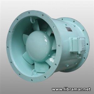 bulkhead installations and sometimes in a cowl for machinery space supply and exhaust systems where the pressure required is small. bulkhead installations and sometimes in a cowl for machinery space supply and exhaust systems where the pressure required is small.
For maintenance, fans must be located for easy accessibility to the motors. Many motors are provided with two-speed controls to permit reduction in supply air during cold weather. Motors are selected for 40 °C ambient temperature except when located where high temperatures prevail, in which case they may be selected for 50 °C or 65 °C ambient temperatures. Axial and propeller fans generally are provided with waterproof or totally enclosed motors.
 The interior environment aboard ship is controlled to provide an atmosphere which is agreeable to the operating personnel, machinery and equipment, cargo and ship stores, and passengers. The environment may be modified by means of ventilation, heating, cooling, and dehumidification or by any combination of these means. Additionally, the elements of noise and vibration must be controlled. The means of controlling these environmental factors must be as reliable, simple, and maintenance free as practical, consistent with the desired results.
Ventilation is the process used to provide fresh outside air to various spaces within the ship. The air is distributed by means of a duct network and suitable weather openings in the ship's envelope. The type of ventilation used depends upon the nature of the space and the service of the ship. The fresh air may be supplied by natural draft or mechanical means and is provided for the removal of heat, noxious or explosive vapors, and to assure an adequate supply of oxygen to personnel. The quantity of air required for each space ventilated is determined by heat transfer or empirical calculations.
") This article continues to discuss the shipboard alarms and protection devices. And now, let us look at sensors starting with level indicators. These monitor liquid level in fuel tanks, lube oil tanks, boilers and the like. The simplest systems are activated by the liquid itself. The device is activated by the level of fluid rising or sinking above or below the set safety levels. When this occurs, a sensor sends a signal to the warning devices, coupled usually with the indicator. One of the most important level alarms on board ship monitors boiler water level. It is critical to maintain right water level in boilers, especially in high-pressure water tube boilers to ensure safe operation.
A very dangerous situation can rapidly arise if the water quantity inside the boiler is not maintained at the correct level. There are visual level indicators as well as alarm systems monitoring the water level to ensure that the level is within set safety limits. Once we are dealing with boilers, we must mention a unique sensor in the alarm circuit known as the flame-out alarm system. A sudden loss of flame inside the boiler can lead to many undesirable consequences. Therefore, optical systems, or flame eyes, provide continuous monitoring of presence of fire and will give instant warning should the flame go out...
 We all understand that the failure of the shipboard machinery may and will result in avoidable and expensive disasters. Do they occur due to bad design, inadequate maintenance or incorrect operational procedures? Experience shows that a large number of machinery breakdowns occur due to a mistake in operation and maintenance of the alarm systems and protection devices.
Yes, engines, generators, boilers, compressors do break down, sometimes fatally damaged because their alarm systems and protection devices monitoring them have been prevented from working, sometimes deliberately disconnected, sometimes clogged up with paint and forgotten, abandoned without checking for long periods of time.
This, of course, is asking for trouble, when only a little attention by duty engineers could avoid an unforeseen incident resulting in possible injuries to people, machinery breakdowns, upsetting the commercial operation of the vessel, leading to extra work load for ship's personnel. Things can go wrong at any time.
|