 Have you ever wondered why the command center of the ship is called a “bridge”? The reason actually comes from history. We can start by going back in time right back to the early days of sail. Ships were a lot smaller and of course steered by a rudder, connected to a tiller, which was operated by the coxswain.
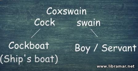
The term coxswain literally translates as servant of the boat. The area that housed the tiller became known as a cockpit or literally the pit where the controls of the boat are located. This has continued into modern day as the area of any vehicle where its controls are located. The cockpit of an airliner is probably the most well-known example. But you also find cockpits in spacecraft and cars, particularly F1.
Over time, the tiller was replaced by wheel; instead of connecting directly to the rudder, the wheel connected using ropes and pulleys. This gave in the distinct advantage of being able to be displaced from the very stern of the ship. At the same time, the design of the entire ship was also changing. Ships were growing ever bigger and their hulls were getting covered by more and more decks.
The biggest deck was the one covering the entire ship – it was the main deck. The one that we are interested in, however, is the quarter deck, i.e. the one aft of the main mast. Famously, it was from the quarter deck that Horatio Nelson was shot and fatally wounded at the battle of Trafalgar on 21st of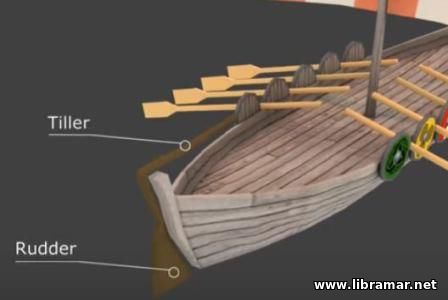 October 1805. For our purposes today, however, the quarter deck was the deck that housed the ship’s wheel. Just like the tiller, the wheel was often operated by the coxswain. October 1805. For our purposes today, however, the quarter deck was the deck that housed the ship’s wheel. Just like the tiller, the wheel was often operated by the coxswain.
With ships increasing in size, the coxswain had many jobs on board. When operating the helm, he was known as the helmsman. Unlike smaller boats, the coxswain was not in charge of the whole ship. He now fell under the command of the master or the captain. The captain would give orders and the helmsman would execute those orders. The entire control arrangement had grown in size from the early days of just a tiller and a coxswain – now we have added in a captain and the ship’s wheel not to mention the other officers, lookout, and ever increasing crew.
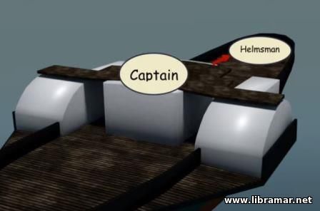
Despite the growth, the arrangement did still remain on the quarter deck at the aft art of the ship. The raised profile of the quarter deck meant that the captain could walk around getting a good view over the whole vessel as well as the seas around the ship. He could give verbal orders to the helmsman all the while walking around.
 At some point the wheel was enclosed by a small structure which became known as the wheelhouse. The helmsman would be inside the wheelhouse, but the captain often remained outside preferring to get a better view all around. It was also easier to direct the other crew from outside. We are now talking about crew operating sails, guns, anchors, and all of the other ship’s equipment. Of course, wheelhouse is another term that has continued into modern day’s usage as the room that houses the controls of a vessel. It is most obvious on smaller boats like fishing bats, tugs, or small work boats, but it is also present on large ships as a part of the modern bridge. At some point the wheel was enclosed by a small structure which became known as the wheelhouse. The helmsman would be inside the wheelhouse, but the captain often remained outside preferring to get a better view all around. It was also easier to direct the other crew from outside. We are now talking about crew operating sails, guns, anchors, and all of the other ship’s equipment. Of course, wheelhouse is another term that has continued into modern day’s usage as the room that houses the controls of a vessel. It is most obvious on smaller boats like fishing bats, tugs, or small work boats, but it is also present on large ships as a part of the modern bridge.
As we move closer to the modern day, we know that wind power eventually gave way to steam – sails were first replaced by paddles, and the first paddle steamer was born. Paddle steamers are recognizable by their large wheels at either side. The wheels turn, propelling the ship forwards. Steamers were often still steered by rudder though some of them did have the independent paddle wheels which could run at different speeds to help with turning but, particularly at high speed, a rudder was better.
For steering, the same personnel arrangement also applied. The wheel was operated by the helmsman who took orders from the captain, but now there was a problem. From the captain’s traditional position on the quarter deck the view was now somewhat obstructed by the paddle houses. He could still give orders but could not properly see where the ship was going. The obvious solution would have been to climb on top of one of the paddle houses to have a great all-around view. Fortunately, there was a ready access as engineers needed access to the top for inspecting the addle blades. The captain could still climb up and still give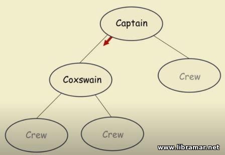 the verbal orders to the helmsman for steering. the verbal orders to the helmsman for steering.
In the interest of efficiency a bridge was often built connecting the two paddle houses together. This started as a bridge in the most literal sense and became the ship’s bridge as we know it today. The captain could command the ship from the bridge sending steering orders to the wheelhouse. And engine orders to the engineers.
As time moved further, the paddles gave way to propellers but the concept of the bridge remained. Accommodation areas replaced the paddle houses, and the bridge remained above. Further developments enhanced the capabilities of the bridge. Remote operation evolved allowing the steering to transfer to the bridge itself. Not just the wheel but the entire wheelhouse was literally built on the bridge. As engine controls became remote as well, these were added to the ever-expanding wheelhouse. For maneuvering, some ships would extend the bridge right to the center of the ship creating wings.
Of course, as navigation itself was conducted from the bridge chart room was also needed. The captain could plan the ship’s voyage and monitor his position from the chart room. With the invention of radio communications ships needed a radio room. In the beginning, it was simply located near the bridge. But, as radio navigation became important, the radio room itself was built onto the bridge.
 And now, we are finally approaching modern day configuration of a ship’s bridge. The bridge contains all the necessary elements for the control of the ship. You have got the wheelhouse which contains the controls for all of the equipment. The chart room contains the charts although this is now often condensed into a chart table within the wheelhouse or even to just to a computer display now, as electronic charts are gradually taking over. The radio room contains all radio communication equipment although, again, this is often just a terminal within the wheelhouse itself. And now, we are finally approaching modern day configuration of a ship’s bridge. The bridge contains all the necessary elements for the control of the ship. You have got the wheelhouse which contains the controls for all of the equipment. The chart room contains the charts although this is now often condensed into a chart table within the wheelhouse or even to just to a computer display now, as electronic charts are gradually taking over. The radio room contains all radio communication equipment although, again, this is often just a terminal within the wheelhouse itself.
The wings extend out from either side of the wheelhouse giving the officer a good view down the side of the ship. Sometimes, there are even duplicate controls on the bridge wings, allowing the entire ship to be controlled from the wing itself. Above the wheelhouse you have the compass platform and this is where the binnacle is located, which houses the magnetic compass. Keeping it above the wheelhouse keeps it as far as possible from the other metal on board.
The modern bridge is a collective term for all of these control elements together. Although the original reason to describing it as a bridge has long gone, the term remains in use today.
 You may or may not have noticed that ships are commonly referred to as “she” rather than “it”. There are plenty of jokes about why ships are referred to as feminine but let us try and find the real reason why.
The English language is horrifically complex; it has evolved over centuries taking influence from many other different languages. A lot of words come from Latin where the word for “ship” is “navis”. Interestingly, an old constellation in the southern sky was the agronavis , or the ship argo. Nowadays, that is divided up into three constellations – Carina, Puppis and a Vela.
Anyway, back to language. Latin assigns a gender to a lot of words with “navis” being designated feminine. Now, you would think that this could lead to a natural association with ships being feminine but Latin by no means is the only influence on the English language. If we take a look at the French name “bateau”, arguably far more similar to “boat” than “navis” is to “ship”, that is actually a sign of masculine gender. Ships like Ile de France were quite confusing as their name comes from the region which is feminine but the vessel itself carries a masculine gender. that this could lead to a natural association with ships being feminine but Latin by no means is the only influence on the English language. If we take a look at the French name “bateau”, arguably far more similar to “boat” than “navis” is to “ship”, that is actually a sign of masculine gender. Ships like Ile de France were quite confusing as their name comes from the region which is feminine but the vessel itself carries a masculine gender.
Similar, in Spanish Columbus’s ship La Santa Maria was a masculine gendered vessel carrying a feminine gendered name. It seems that even in the roman languages the name given to a ship has no relation to the gender of the noun itself. Indeed, if you look at modern ships names, there is certainly no inference that the ship itself is gendered.
HMS Queen Elizabeth is clearly named after a female, yet the next ship in the class is HMS Prince of Wales clearly named after a male. However, at the christening ceremony Her Majesty the Queen herself referred to the ship as female – “I name the ship 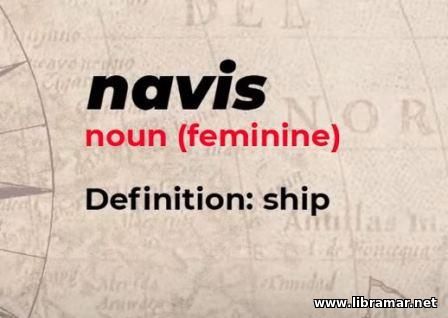 Queen Elizabeth. May God bless her and all who sail in her”. The same thing happened at the christening ceremony of the HMS Prince of Wales - the Duchess of Cornwall consistently referred to the ship as “she”. Queen Elizabeth. May God bless her and all who sail in her”. The same thing happened at the christening ceremony of the HMS Prince of Wales - the Duchess of Cornwall consistently referred to the ship as “she”.
The christening ceremony is the tradition when ships are launched. In Britain, the ship is blessed, given its official name and a bottle of champagne is broken against the hull. Interestingly, HMS Queen Elizabeth I has a bottle of whiskey broken instead to honor her Scottish heritage. The ceremony itself has been around for centuries and was always done for religious and superstitious reasons. In days gone by sailors believed they needed all they luck they could get. They wanted to appease the Gods of the sea to try and ensure they got home safely. Of course, now modern technology, sophisticated weather forecasting and proper passage planning has increased the safety of ships enormously.
You could argue that the christening ceremony is no longer needed to give that psychological boost that that it once did. We do continue it though, because it is a tradition. Traditions keep us in touch with the past and arguably without them we would live in quite a plain and clinical world. So, back to the main question – why ships are referred to as “she” – it could come from the Latin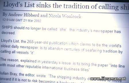 heritage of the word itself, but more likely it has come from the same place as the naming ceremony – tradition. heritage of the word itself, but more likely it has come from the same place as the naming ceremony – tradition.
Most ancient sailors were men and they named the ships after the people they loved. At the naming ceremony, the ships were probably bestowed a gender based on that name. Combining a name that they love with the mother’s protection that it was hoped the ship would provide led to the feminine association we have today. We believe it was the act of christening that has led to ships being referred to as “she”. It has been reinforced over time with phrases such as mothership referring to a large vessel that launches others, and sistership referring to ships of same class. Of course, now the debate is open as to whether this should all change. Some shipping registries and museums already have eliminated all personifications of ships and changed to “it” instead.
 Ships have a reputation for being large bulky lumps that slowly plot around the world even a passage from San Francisco to Southampton on a modern ocean liner now takes the best part of a week. What is it about ships that makes them so slow? In terms of physical size ship’s engines are enormous. They are so big that the larger ones are typically known as cathedral engines – the Emma Maersk is powered by one of these. She is an E-Class container vessel almost 400 meters long and was the largest container ship when she was launched back in 2006.
Of course, since then Maersk have introduced the Triple E Class which is slightly wider and longer and other companies have bought out ships even bigger; still her engine weighs more than three hundred tons and pumps out a whopping 109000 horsepower. Now, it is easy to compare that to a car as they all publish the horsepower of their engines. The typical cars you are looking at about hundred horsepower depending on the configuration you have chosen. At the extreme end, you have got Formula 1 cars which can be pushing a thousand horsepower.
It is a little trickier to compare that to an aircraft as they use jet engines which produce thrust instead of the mechanical horses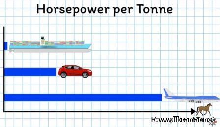 that we use anywhere else. The math is complex, but the best estimates are found - the typical 747 engines are 150000 HP mark. So, for power it makes sense that the plane is the fastest but the ship comes second and she is still slower that the car. So there must be more to it than just the horses. that we use anywhere else. The math is complex, but the best estimates are found - the typical 747 engines are 150000 HP mark. So, for power it makes sense that the plane is the fastest but the ship comes second and she is still slower that the car. So there must be more to it than just the horses.
With movement and things another factor always makes an appearance – mass – it is in the energy formula with kinetic energy being half MV squared and it forms acceleration force being mass times acceleration. So, how we can add mass into this discussion? We can look at horsepower per ton instead. For the plane we can take the 474 – they come in anywhere between three and five hundred tons and are powered by four of those jet engines. A crude power gives the power per ton, let’s say, 1200 horsepower per ton. The car we said was around 100 horsepower typically and you can assume in normal car weighs between one and two tons, and averaging that out gives you about 75 HP per ton.
Of course, with F1 cars they are somewhat lighter and more powerful, so their figures are closer to the figures we got for the airliner. Now the ship, fairly obviously, she will weigh the most. The fully loaded Emma Maersk will weigh around 200000 tons, with her engines delivering 109000 HP, we will calculate the power per ton as 0.5 HP/ton. The vehicles are now starting to settle in the correct order. The plane is still ahead, the car is second and the ship is training a long way behind. But fir the ship, from here it only gets worse.
Do you remember working out terminal velocity at school – is when the force produced by an engine matches the resistance  force from the medium. The object is moving through. For example, you drop a ball and it will fall faster than if you drop a feather, the wind resistance of the feather is much greater so its velocity ends up being slower. The same applies with vehicles. The plane experiences air resistance, the car – a combination of air resistance and friction with the ground, but the ship is moving through water a comparatively dense medium. This means she is experiencing the greatest force against her. force from the medium. The object is moving through. For example, you drop a ball and it will fall faster than if you drop a feather, the wind resistance of the feather is much greater so its velocity ends up being slower. The same applies with vehicles. The plane experiences air resistance, the car – a combination of air resistance and friction with the ground, but the ship is moving through water a comparatively dense medium. This means she is experiencing the greatest force against her.
The drag equation explains that drag is proportional to a cross-sectional area and the square of the speed. The cross-section will get from the breadth of the ship times its draft, which we can assume to e a constant for most ships. Of course, if you reduce the draft, like when there is no cargo, the ship will be able to go faster as there is less drag. Otherwise, drag is determined by the square of the speed. You double the speed, you quadruple the drag. You can sort of assume the force produced by the engine is constant. There are variations due to the water flow, but we can ignore those for now.
All the while the engine produces more force than the resistance. The ship will accelerate as she speeds up. The drag increases according to the square of the speed. Once the drag force matches the engine force, no more acceleration occurs. The ship has reached terminal velocity. For the Emma Maersk this is around 25 knots and that is typical for most large ships. For smaller ships, this is typically slower and that is because their engines produce more power. But crucially the cross-section does not reduce in proportion to that change in engine power.
There are ferries that do go significantly faster than normal ships, some of them are called fast cats, which is short for fast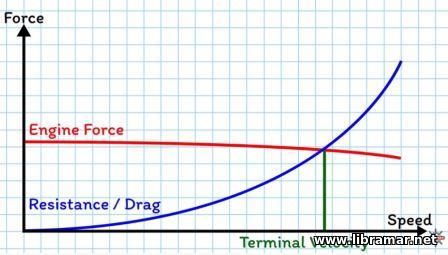 catamaran and a catamaran is just a boat that has two hulls. Instead of a single box-shaped hull the cat has two thin hulls. The separation between them produces the transverse stability that they need and the buoyancy is just produced by the combined underwater volume of both hulls. Clearly, there is less buoyancy which means less carrying capacity which is why they are usually only passenger ships. They key here is that you have drastically reduced the cross-section that produces the underwater drag. Reduce the drag and you will increase the theoretical maximum speed add on a few jet turbines and you’ve got yourself a ferry that is capable of speeds far higher than a typical ship. catamaran and a catamaran is just a boat that has two hulls. Instead of a single box-shaped hull the cat has two thin hulls. The separation between them produces the transverse stability that they need and the buoyancy is just produced by the combined underwater volume of both hulls. Clearly, there is less buoyancy which means less carrying capacity which is why they are usually only passenger ships. They key here is that you have drastically reduced the cross-section that produces the underwater drag. Reduce the drag and you will increase the theoretical maximum speed add on a few jet turbines and you’ve got yourself a ferry that is capable of speeds far higher than a typical ship.
And what about small speed boats? Well again, they reduce the cross-sectional area allowing higher speeds but rather than change the shape of the hull, they are designed to rise above the water instead of pushing through it. We call it planing above a certain speed the water flow lifts the hull, reducing the cross-section reduces the drag and increasing the speed. Hydrofoils do a similar thing except they have an underwater wing to produce the lift. At slow speeds the whole hull creates resistance; as the speed increases, lift is generated lifting most of the hull clear, reducing the cross-section and increasing the speed.
 Water, weather, wear – these are three problems the vessel is exposed to and they directly influence the lifetime of the paint systems which should protect your ship against corrosion. Ships today have smaller operational crews and faster turnaround in ports than ever before. Consequently, the time that can be devoted to maintenance of shipboard coatings has been reduced drastically. Paint systems applied during newbuilding period of the vessel are, in general, high quality paints. However, paint systems will deteriorate and, therefore, coatings need maintenance – in sake of safety, operational efficiency or just for cosmetic reasons. After all, the ship is also your home.
The protective coatings must be periodically maintained like engines and mechanic equipment. Preventive maintenance will reduce the extent of corrosion and also the interval between the maintenance jobs. But, is it at all possible to carry out rational and economical coating maintenance with the limited resources available on board ships today? Yes, it is, but there are few steps which should be followed.
Step 1 - Planning
Before you start the shipboard maintenance, you have to identify the defects in the paint system and find out what exactly needs to be done, which tools you will need and if you have correct quality and quantity of paint on board and other things. The weather conditions and ship operations shall also be taken into account. to be done, which tools you will need and if you have correct quality and quantity of paint on board and other things. The weather conditions and ship operations shall also be taken into account.
Step 2 – Safet
If you can do your job in a safe way, you protect yourself against accidents and the results of the work carried out will improve. Is your safety equipment in good condition? Use a boiler suit, safety boots, wear gloves, ear protection and mask, goggles and, of course, a helmet. Use the correct protection equipment for the right job. When you work in confined spaces, make sure there is proper ventilation and lighting, and make sure that the pre-treatment and application equipment is in good condition
Step 3 – Surface Preparation
Removal of oil, grease, and fat is done by an emulsifier since wiping with rags soaked into solvent redistributes rather than removes fatty substances. This preparation is very important since oil, grease, fat and salts cannot effectively be removed by mechanical cleaning. After this, fresh water washing has to be done in order to remove salts. When the surface is dry, corrosion products, thick paint layers and loosely adhering paint can then be removed.
 This can best be done by mechanical tool like a scraper, which is suitable to remove thick rust layers and paint but should be followed by a wire brushing or disc grinding. Other tools could be the needle gun, which is good in removing hard rust scale or heavily rusted layers of paint; this tool tends to make indentations in steel. A good wire brush is ideal for removing rust, but be aware that too much brushing will polish the surface and poor adhesion of the paint will be the result. This can best be done by mechanical tool like a scraper, which is suitable to remove thick rust layers and paint but should be followed by a wire brushing or disc grinding. Other tools could be the needle gun, which is good in removing hard rust scale or heavily rusted layers of paint; this tool tends to make indentations in steel. A good wire brush is ideal for removing rust, but be aware that too much brushing will polish the surface and poor adhesion of the paint will be the result.
The disc sander is also a suitable tool for feathering edges and sanding intact coatings. The edges of the repaired areas should be feathered smooth. The surrounding intact coating should also be sounded in order to secure adhesion. For smaller or difficult areas this can be done by hand, bigger areas – with a sander; note that the sanding may be omitted for acrylic coatings. But make sure that the correct type of tool is used for the right job.
Step 4 – Paint Preparation
Before you start to handle or use any paint, learn all that is worth knowing about this product and the correct and safe use of it. Look into your maintenance manual and specification, and also in the product data and safety datasheets. Ensure that the paint is stored under correct and safe conditions. Make sure that the paint locker is well ventilated. Check the specification and select the right products. Use the correct cure agents and thinners and use them in the correct quantity.
Step 5 – Paint Application
Then, on the dry and dust-free surface the first coat of the repair system can be applied. You have to stir paint with the mixer before you can apply it. The paint should have a completely uniform color with no sediments. Then, stir for an extra 30 seconds. Note that wrong mixing will result in poor performance. Primers are ideally applied by brush and, if possible, using a minimum of two coats within the same working day in order to obtain enough paint protection after the pre-treatment. before you can apply it. The paint should have a completely uniform color with no sediments. Then, stir for an extra 30 seconds. Note that wrong mixing will result in poor performance. Primers are ideally applied by brush and, if possible, using a minimum of two coats within the same working day in order to obtain enough paint protection after the pre-treatment.
Unless spray application equipment is on board, the best way is to apply paint by brush. The brushing action assist the paint to penetrate the surface and, beside spray application, is the only suitable method to apply primers. The film thickness which you apply per coat by brush is approximately 40 microns. This means that you need more than two coats to protect the pre-treated steel. For the correct number of coats you have to consult the specifications in your maintenance manual.
The most common paint application tool on board ships is probably the roller, but it should not be. Roller application leaves an uneven form and numerous thin spots. Corrosion will start in these weak areas and continue on the paint system. Sooner or later, heavy rust can be observed. When enough primer coats have been used, the top coat can be applied. Correct mixing of the top coat is also necessary. When you mix the paint in a correct way, the application gives a much better result.
After the final application, close the paint drums in a right way, and store them again properly in the paint locker. Clean your application tools using the correct method so that you can use them again next time. A lot of work, but with satisfying result; perhaps troublesome, but necessary.
 Blistering is a result of the solvent entrapment. Painting on top of a bit of rust or when you apply film in a tool thin film gives bad results. And, paint application over thicker layers can result in lifting, flacking, or cracking. Blistering is a result of the solvent entrapment. Painting on top of a bit of rust or when you apply film in a tool thin film gives bad results. And, paint application over thicker layers can result in lifting, flacking, or cracking.
Keep Maintenance Simple
Keep intact coatings free from dirt and salt. Maintenance by cleaning is also a worthwhile activity. The removal of oil, grease, salt and other contamination will prolong the lifetime of the coatings. Preventive maintenance will utilize man-hours and equipment more economically. Do the maintenance operations thoroughly and remember the right sequence. When you follow these simple steps, you work and live safely on board the well-maintained vessel.
 Naval architects and engineers in structured organizations are frequently excluded from participating in the contracting and financing arrangements of vessel construction. This exclusion is most unfortunate and it is anticipated that this section will assist naval architects and engineers in contributing to these arrangements.
Far too often the approach to vessel selection and financing involves lawyers, accountants, financial planners, and ship construction people working independently of each other without the continuing interchange of ideas that is so essential during the planning stage.
The widest knowledge of any proposed vessel construction and the fullest participation in the mission aspects of new vessels provide the best climate for producing the most effective design and construction.
If continuing interaction of the interested parties is not feasible, the next best thing is to have those entering the field of vessel construction understand fully the various contributions of the lawyers, the accountants, the financial planners, and the operators to  the design, and the documents and instruments developed over the years to ensure the continuum of events which must occur timely to produce the desired vessel within the desired time at an acceptable price. With the intellect considered to be the prerequisite of such understanding comes the patience to accept a less perfect alternative when it is more important to see the project move onward. the design, and the documents and instruments developed over the years to ensure the continuum of events which must occur timely to produce the desired vessel within the desired time at an acceptable price. With the intellect considered to be the prerequisite of such understanding comes the patience to accept a less perfect alternative when it is more important to see the project move onward.
Accordingly, this section is proceeding on a format which is intended first as a narrative of a typical ship design genesis, its subsequent contracting and construction, and its delivery and operating inception. After this over-simplified case history approach, a more detailed discussion of the legal and financial aspects and impacts, including the documents usually involved in such transactions will be presented.
Where deemed appropriate, a sampling of alternative approaches will be included, all to show the reader that the kinds of agreements which can be made between a purchaser and a builder or between a financier and a purchaser/borrower are limited only by the law of the land and the ingenuity of the parties dealing in the matter - the assumption being in all cases that the objective is the best product at the least all-inclusive cost to the owner.
Also, where the narrative leads to identifiable problem areas, sufficient analysis will be outlined to permit understanding and insight into the course of these problems so that the naval architect or marine engineer might be better prepared to avoid controversial approaches in preparing ship construction documents for the clients or principals.
A significant number of naval architects, engineers and others are directly involved in United States shipbuilding and shipping business practices which differ in many respects from those in other shipbuilding countries. Although this chapter discusses international costing and contracting arrangements to some extent it is primarily concerned with U. S. practice.
To the extent considered necessary, reference is therefore frequently made to specific United States rules, organizations and operating procedures. At the same time, the general discussions apply equally to all international shipbuilding and shipping.
 When dealing specifically with the United States government, those procurements made directly by the U.S. Navy and the U.S. Coast Guard are generally so identified; when the term government aid is used it generally means the government is not procuring the vessel but that the owner, buyer, or purchaser has arranged a construction differential subsidy (CDS) for the shipbuilder and/or obtained a government insured mortgage or other benefits available under the Merchant Marine Act. When dealing specifically with the United States government, those procurements made directly by the U.S. Navy and the U.S. Coast Guard are generally so identified; when the term government aid is used it generally means the government is not procuring the vessel but that the owner, buyer, or purchaser has arranged a construction differential subsidy (CDS) for the shipbuilder and/or obtained a government insured mortgage or other benefits available under the Merchant Marine Act.
In discussions of shipbuilding costing and contract arrangements, a number of terms are used that have specific connotations in this aspect of the shipbuilding process. The following definitions can be considered to apply.
Architect of Contract: A term borrowed from the legal profession to indicate the person or entity that authored the contract document.
Builder: In this text, builder, contractor, and shipyard are used synonymously. It is the entity that signs the construction contract and undertakes to physically build the vessel. The various forms are used as these terms are encountered in invitations, contracts and specifications.
Owner: This term is used to identify the buyer of a vessel to be constructed. In the parlance of MarAd contracts the term purchaser is usually substituted for buyer. Primarily, the intent is to name the party who selects the design and causes the initiation of the contract to build. It is recognized that in leveraged lease situations the owner of record of the constructed vessel may be someone or some group having only a financial interest. In such cases owner as used herein is the charterer.
Naval Architect: Anyone having decision authority over the design of the vessel to be constructed or reconstructed. ln-house naval architects are those on the wage payroll of the shipowner or entity contracting for a vessel. Outside or Contract naval architects are those persons whose business is the design and engineering of vessels, and who contract with owners or shipyards to perform their services for a fee.
Design Agent: A term used interchangeably with an outside or contract naval architect. It has come into use as shipyard designs have become prevalent. Shipyards are frequently design agents. They do employ naval architects, and those who work at design are usually in the engineering department or the planning department.
Reps: Abbreviation for representatives; as, for in¬stance, owner's reps are the inspectors and plan approvers working on-site during ship construction. 
Lead Ship: The first vessel built to a new set of plans and specifications. It is not necessarily the first vessel delivered because under circumstances of the order being allotted to two or more yards, the first vessel in one of the other yards may be delivered first. This occurs because of better production methods, or because of unforeseen delays in the lead yard.
Following Ships: Ships built to the same plans and specifications whether in the same yard as the lead ship, or in other yards, are following ships.
Berth Term: This refers to dry cargo liner operations utilizing publicly issued schedules of port calls.
Cease and determine: A phrase used in Maritime contracts to indicate a full unconditional stop action plus an inventory of the financial position as of that moment.
 On board ships equipped with machinery developing power for propulsion and auxiliary purposes, personnel are subjected to vibration. The vibration may cause annoyance, physiological damage to body organs, psychological disturbance of the crew or damage to shipboard equipment.
The effect of vibration upon equipment installed aboard ship has been one of the major factors resulting in premature failures of equipment which has previously proved satisfactory in land-based installations. The equipment supplier must consider the vibration aspect of the shipboard environment in the design and construction of marine hardware.
A magnitude of vibration which can do no harm to equipment or structure can, however, be a great nuisance to the crew. The degree of human perception to vibration in the frequency range of 30 to 4800 cycles per minute is a function of the amplitude of the vibration. Frequencies below 0.5 Hz may cause motion sickness.
While it is difficult to define precisely acceptable limits of intensities of vibration, two figures in this article identify vibration zones which may be used as a guide in determining general acceptability. Zone A defines that area within which a high probability of vibration difficulties exist; Zone С defines that area within which no vibration difficulties are anticipated; Zone В defines that area within which the subjective nature of vibration does not permit a reasonable assurance of acceptability.
 The human ear has certain interesting characteristics. The normal hearing range for a young person extends from about 20 to 15,000 Hertz (Hz) (cycles per second), with the greatest sensitivity around 1,000 Hz. Aside from the noise attributes of loudness and annoyance, there is the factor of physical tolerance to noise, that is, the noise sound-pressure levels which the ear can stand without discomfort or damage.
The effect of noise on the human being with regard to hearing loss and communication has been studied and design criteria established through extensive habitability research in naval ship design. The effect of noise annoyance is, however, not as well defined. The wide range of noise levels' which various persons find disturbing makes this aspect of noise control more subjective and difficult to define. Factors which influence a person's reaction to noise include interest of the listener in the sound, whether the noise is unnecessary and could be avoided, the degree to which the listener can disregard the noise, the activity with which the noise interferes, the character of the listener.
For the more noisy spaces aboard ship, it has been determined that people can readily adjust to various  environments and actually consider them normal, once they are conditioned to accepting them, provided the environment includes no hostile sounds. How well the naval architect can handle the problem of acoustical habitability depends largely upon how well he can control the magnitude of sound levels and how much he can shape the noise spectrum in any of the various ship's spaces. environments and actually consider them normal, once they are conditioned to accepting them, provided the environment includes no hostile sounds. How well the naval architect can handle the problem of acoustical habitability depends largely upon how well he can control the magnitude of sound levels and how much he can shape the noise spectrum in any of the various ship's spaces.
The reduction of noise within certain spaces may produce counter-productive results. For example, staterooms normally receive a high degree of isolation from passageway noise, however, the resultant number and location of general alarm bells must be carefully reviewed to assure audibility within all staterooms. Also, the enclosing of machinery control stations has prompted some reaction from operating personnel that not hearing the machinery has degraded their effectiveness.
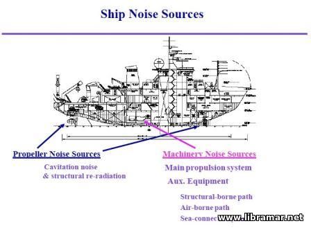
The major sources of noise generation aboard ship may be categorized into flow generated noise and mechanically generated noise. Each of these general categories contains several elements each of which must be considered by the designer to preclude objectionable noise conditions aboard an operational ship. Flow generated noise is produced by a fluid in motion. The fluid may be either a liquid or gas and may be either within the ship envelope or external to it.
Noise Generated by Ship Mooing Through the Water
Flow of water around the hull of a ship is almost completely turbulent, particularly in the bow and stern areas. The 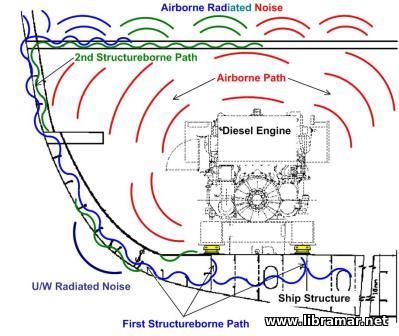 turbulent water flow path produces pressure fluctuations which tend to drive the hull plating into vibration. The resultant noise may be transmitted within the hull either as airborne noise or as structureborne noise. Discontinuities of the hull such as sonar domes, sea chests, and shaft struts function to increase the turbulence within the boundary layer thereby tending to be sources of external flow noise. turbulent water flow path produces pressure fluctuations which tend to drive the hull plating into vibration. The resultant noise may be transmitted within the hull either as airborne noise or as structureborne noise. Discontinuities of the hull such as sonar domes, sea chests, and shaft struts function to increase the turbulence within the boundary layer thereby tending to be sources of external flow noise.
Propeller Generated Noise
Several different types of noise may be generated by the ship's propeller. The two types of propeller noise associated with fluid flow include cavitation and vortex shedding. When a ship's propeller is rotated at high speed cavities can form and collapse radiating a loud and continuous noise. Also vortices are shed from the trailing edges of the propeller blades. If the frequency of this shedding corresponds with a resonant frequency of the propeller blade the blade vibration will radiate a loud ringing noise.
Fluid Flow Noise
The noise sources within piping and duct systems are similar to those produced by the ship moving through the water and the propeller. The flow of fluid through a piping system may produce noise due to turbulence, cavitation and vortex shedding. In piping systems the noise may be intensified by the organ pipe effect of the pipe or duct. Restrictions or obstructions in the fluid flow path which increase the velocity are prime sources of cavitation and turbulence generated noise. Dampers and splitters within ventilation ducts may also produce noise due to vortex shedding.
Mechanically generated noise usually originates in rotating and reciprocating machinery. The sources of such noise may be the result of improper balancing, excessive tolerance between mating parts such as gears or the result of loose or worn parts. The characteristics of the machine and the noise produced may provide an indication of the problem area.
Design Implications
The acoustical aspects of controlling the ship's interior environment must be included at the beginning of the design process. In many cases, it is extremely difficult and expensive to correct a noise problem whereas the impact of 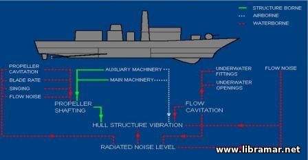 precluding the problem at the early design stage would be minimal. precluding the problem at the early design stage would be minimal.
When addressing the acoustic or noise considerations both the noise source and the transmission path must be reviewed. Control of noise at the source may be accomplished by improved dynamic balance of rotating machinery, limiting velocity within fluid systems, avoiding turbulence within fluid systems, improved tolerance between mating parts, and application of suppression material to the noise source. In addition, the noise level within spaces such as staterooms may be controlled by locating them as remote as practical from spaces having a higher noise level. For example, it would not be prudent to locate a stateroom adjacent to a fan room.
Noise may be transmitted from the source to other areas via the structure as vibration, as airborne noise or as fluid-borne noise. Structureborne noise usually originates at machinery or equipment foundations. Transmission of noise from a machine to the supporting structure may be reduced by mounting the unit on resilient mounts or distributed isolation material.
Where such type mountings are used, isolation of the connecting piping or ductwork must also be accomplished. When resilient mounts are employed, care must be taken to assure the natural frequency of the mount does not coincide with the exciting frequency of the vibration source.
 Airborne noise may be reduced by locating the offending unit within a space lined with sound absorbent material or, as in the case within the engine room, as remote as practical from the operating station. Airborne noise may be reduced by locating the offending unit within a space lined with sound absorbent material or, as in the case within the engine room, as remote as practical from the operating station.
Fluidborne noise may best be controlled by eliminating the source where practical. If a large pressure drop is induced by a single orifice in a piping system, consideration should be given to a multiple-step orifice thereby reducing the velocity through each step. If the source of the noise may not be eliminated as in the case of ventilation fans, absorbent material may be installed in the ductwork or, in some cases, the ductwork must be increased in mass to reduce the amplitude of response of the ductwork to the vibratory excitation.
With respect to naval vessels, acoustical considerations may extend well beyond the element of habitability due to the nature of the ship's function. The methods employed aboard submarines, for example, for controlling noise are several orders of magnitude more extensive than those normally encountered in merchant ship practice.
 Economy in ship construction and improvements in the serviceability and service life of ship structures can be enhanced if several principles basic to welded construction are observed in the design process. These principles are derived both from service experience and from studies of the causes and prevention of structural failures in ships.
Base Metals
The mechanical toughness and corrosion properties of the base metals selected should resist excessive degradation from welding and forming practices. This precaution is particularly applicable to those materials whose properties have been enhanced by heat treatment or cold work. In addition, when materials of widely differing corrosion resistant characteristics are joined, possible  adverse galvanic corrosion effects should be considered. adverse galvanic corrosion effects should be considered.
Examples of degradation which may be encountered are:
• Loss of toughness in the HAZ of some steels, particularly some higher strength steels, where weld procedures with excessively high heat input rates have been used.
• Loss of strength, ductility, and corrosion resistance in the HAZ of the heat treatable aluminum alloys.
• Accelerated corrosion attack on carbon steel located adjacent to an area overlayed with a stainless steel.
• Loss of ductility and toughness in materials subjected to excessive cold forming.
Stress Concentration
Points of high stress concentration such as may be introduced by a flaw or an abrupt change of geometry at an intersection have been identified as potential sources of brittle fracture initiation. Surveys have shown that they can be a primary source of fatigue  cracking which produces many of the nuisance cracks. Such cracks can represent significant cost items in respect to their interruption of normal ship operations, and the time and effort required for their repair. Areas of high restraint where high weld residual stresses can develop should also be minimized. cracking which produces many of the nuisance cracks. Such cracks can represent significant cost items in respect to their interruption of normal ship operations, and the time and effort required for their repair. Areas of high restraint where high weld residual stresses can develop should also be minimized.
Joint Design
The attainment of a sound weld joint and its proper inspection can only be achieved if appropriate clearances are provided. In considering this aspect, the designer should take into account the production weld process and inspection method. Access requirements for some automatic and semi-automatic weld processes may differ among each other as well as be different from shielded-metal arc welding. The extent to which adequate or inadequate access is provided could control the degree and facility to which an automated weld process could be considered which could in turn represent a significant production cost factor.
Overall Design
Direct overall design to minimize the probability of transverse fractures. In some cases this may involve the use of material of superior toughness or the judicious incorporation of designs of special geometry or redundant structure which would interrupt a transversely running crack.
Avoid Excessive Welding - In some cases overwelding may result in the imposition of excessively high welding stresses.
Through Thickness Loading
Since most conventional hull steels are not provided with minimum specified through thickness properties, they may exhibit weakness under such a loading condition. Where through thickness loading in a structure cannot be avoided by a design modification, special materials with enhanced through thickness properties should be considered.
Welding and Nondestructive Testing Symbols
Welding symbols are used to communicate a designer's and fabricator's requirements to those concerned with design, design review, and fabrication of a structure. While preliminary design may require few details of weld joints, the requirement for inclusion of more details increases as the development of plans progress through the preliminary design to contract design and working plan stages.
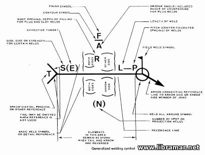 Detail design plans, when used in the shipyard, should contain complete details of the welds and any nondestructive tests that may be required. When plans form the basis of a contract, omission of any special requirements in respect to extent of penetration, finish, post weld nondestructive test examination etc. could lead to disputes between the purchaser and fabricator. When such details are omitted in final fabrication plans of the shipyard, such omission may allow for inadequately penetrated, finished or inspected welds. Detail design plans, when used in the shipyard, should contain complete details of the welds and any nondestructive tests that may be required. When plans form the basis of a contract, omission of any special requirements in respect to extent of penetration, finish, post weld nondestructive test examination etc. could lead to disputes between the purchaser and fabricator. When such details are omitted in final fabrication plans of the shipyard, such omission may allow for inadequately penetrated, finished or inspected welds.
|