 As used herein, the term semi-automatic process means that the electrode is manipulated manually and all other welding parameters including rate of electrode feed are controlled automatically; automatic process means all parameters including electrode manipulation are automatic.
Shielded Metal Arc Welding
SMAW is a process where heat is produced by an electric arc between a covered metal electrode and the work. The arc melts the metal of the electrode and the spray or droplets formed transfer across the arc to coalesce as a molten pool before solidifying as weld deposit. The transfer mechanism involves a combination of complex phenomena of arc physics. The formulation of the 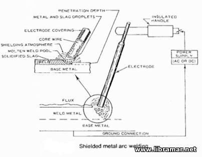 cellulose or mineral base electrode covering assures that the covering will decompose or melt in the arc in an appropriate manner and rate, and accomplish the following: cellulose or mineral base electrode covering assures that the covering will decompose or melt in the arc in an appropriate manner and rate, and accomplish the following:
• provide a gas or slag environment which shields the metal from the atmosphere during metal transfer and solidification; • establish a favorable electrical environment for arc stability;
• provide a slag covering for the deposited molten weld metal which refines the metal and may, in some cases, provide alloying additions; and,
• influence the fluidity of the molten weld metal which in turn influences the shape and contour of the deposited weld bead. Since the covering has a great influence on the transfer and natures of the resulting weld deposit, it is important that coverings be kept free of contaminants such as moisture or grease which could alter their characteristics.
Gas Metal Arc Welding
GMAW is an automatic or semi-automatic process in which a welding arc is formed between the work and bare electrode. The 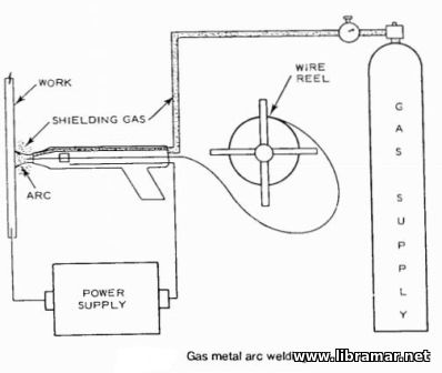 electrode is continuously fed from a spool which may weigh from 0.5 to 23 kg. An inert gas shields the arc and molten weld area from the atmosphere; such shielding is analogous in function to that of the covering in the SMAW welding-Carbon dioxide, argon, or helium or a combination of gases is used for shielding. When argon or helium are used for shielding the process is relatively expensive and is not generally used when more economical welding processes are applicable. electrode is continuously fed from a spool which may weigh from 0.5 to 23 kg. An inert gas shields the arc and molten weld area from the atmosphere; such shielding is analogous in function to that of the covering in the SMAW welding-Carbon dioxide, argon, or helium or a combination of gases is used for shielding. When argon or helium are used for shielding the process is relatively expensive and is not generally used when more economical welding processes are applicable.
Gas Tungsten Arc Welding
GTAW is similar to the aforesaid Gas Metal Arc Process except that a tungsten electrode is substituted for the continuously fed filler metal electrode of the GMAW process; in GTAW the filler metal is provided by a weld rod which is fed so that its end is melted by the welding arc maintained between the tungsten electrode and base metal. Argon or helium is used as shielding 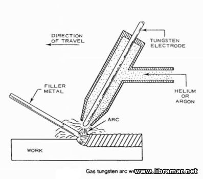 gases. gases.
Flux Cored Arc Welding
FCAW is similar to the GMAW process except that the inert gas shielding is replaced by a flux which is located in the core of the filler wire; the flux, when exposed to the welding arc, provides appropriate shielding and to some extent is analogous to the covering of the electrodes used in SMAW welding. Some variations use CO2 or CO2+ argon mixtures for auxiliary shielding. The process which is primarily used for steels, offers a means for achieving the economy of semi-automatic welding for many applications where the relatively slower but versatile SMAW process was previously 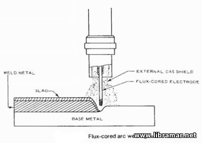 used. used.
Submerged Arc Welding SAW
In this semi-automatic or automatic process an arc is maintained between a continuously fed spool and a work area. The welding zone is completely buried and shielded under a granular flux or melt provided from an independent feed tube. The flux or melt, when molten, maintains an electrical path of high current density which generates a great quantity of heat. The insulating characteristics of the flux concentrate the heat in the weld area and induce significant melting of base metal as well as welding electrode. Under such conditions, high welding speeds, high deposition rates, significant melting of base metal, and deep weld penetration can be achieved. SAW with two- or three-wire electrodes instead of a single wire provides even higher welding speeds and deposition rates.
Because of these features SAW is a frequently used automated welding process in steel ship construction. Common practice in making a sub-assembly of full penetration welds in a panel line is to submerge arc weld a sub-assembly of several plates from one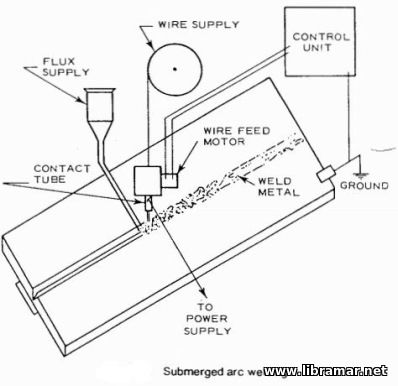 side, turn the sub-assembly and complete each weld from the second side; welding from both sides is usually necessary to assure complete weld fusion. However, SAW welds with sound roots can be made from one side only, thereby eliminating the cost and time consumed in sub-assembly turning and re-welding from a second side. This form of the process designated as one-side welding requires close control of joint fit, plate waviness, and weld parameters. Additionally, a special backing or tape on the back side of the joint is usually necessary to contain the molten weld metal at the root so that it forms a sound weld deposit of satisfactory contour. side, turn the sub-assembly and complete each weld from the second side; welding from both sides is usually necessary to assure complete weld fusion. However, SAW welds with sound roots can be made from one side only, thereby eliminating the cost and time consumed in sub-assembly turning and re-welding from a second side. This form of the process designated as one-side welding requires close control of joint fit, plate waviness, and weld parameters. Additionally, a special backing or tape on the back side of the joint is usually necessary to contain the molten weld metal at the root so that it forms a sound weld deposit of satisfactory contour.
Electroslag, ES and Electrogas EG Welding
These are high deposition rate processes analogous to the SAW and GMAW processes respectively, except that the molten weld pool is contained within movable copper shoes at each side of the weld joint. A variation of the electroslag method, which uses a consumable guide tube instead of a permanent tube has been used for 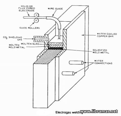 applications such as butt welding of underdeck longitudinals. Because of the exceptionally high deposition rates and large molten weld pools, arrangements are only available for vertical welding. In ES welding, a bar or strip is occasionally substituted for the one or more electrodes. applications such as butt welding of underdeck longitudinals. Because of the exceptionally high deposition rates and large molten weld pools, arrangements are only available for vertical welding. In ES welding, a bar or strip is occasionally substituted for the one or more electrodes.
Exceptionally thick materials may be welded in a single pass and in the case of ES welding, materials in excess of 400 mm thick have been welded in a single pass. Appreciably higher speeds are attained as plate thickness decreases and as thicknesses approach 12 mm welding speeds of more than 10 times those shown are attained. Because of their relatively high heat input rates, ES and EG welding cause a greater degree of grain growth and other metallurgical changes in the weld heat affected zone, HAZ, than other processes. In some cases these may adversely affect HAZ properties, such as toughness, to the extent that use of the process must be restricted.
Stud Welding
SW as used in shipbuilding, is an arc welding process wherein an arc is maintained between a stud or similar piece and the work, for a predetermined time so that both are properly heated. The stud is then brought to the work by spring pressure. A ceramic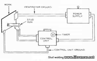 ferrule is sometimes used to provide partial shielding and some contour. The process is accomplished with an automated welding gun, power source, and control panel; the control panel regulates electrical parameters, welding arc time, arc distance, and the imposition of pressure between stud and work at the end of the welding cycle. The process is widely used in shipbuilding for attaching a wide variety of items such as studs, clips, hangers, and insulation pins to structural members. ferrule is sometimes used to provide partial shielding and some contour. The process is accomplished with an automated welding gun, power source, and control panel; the control panel regulates electrical parameters, welding arc time, arc distance, and the imposition of pressure between stud and work at the end of the welding cycle. The process is widely used in shipbuilding for attaching a wide variety of items such as studs, clips, hangers, and insulation pins to structural members.
 Aluminum alloys used in marine construction are readily weldable with the inert-gas arc-welding processes; Gas Metal Arc, GMAW or MIG, and Gas Tungsten Arc, GTAW or TIG. The former process predominates because of its higher production speeds and greater economy. In welding aluminum, particular care should be taken to see that all surfaces in the way of welding are clean and free of contaminants, such as water stains, oxide films, and anodized layers; when present, they may be removed. Preheat is not generally needed except when welding exceptionally thick sections, under conditions of high restraint, when humidity is very high, or when temperatures are below 0°C. For the 5000 series alloys, prolonged preheating or exposure in the 65°C to 200°C range should be avoided, since it could sensitize the alloys to corrosion.
Welding Effect on Base Plate
Welding of the 5000 series alloys, where strength is usually derived from work hardening, produces a zone within approximately 13 mm to 25 mm of the weld where yield and tensile strength of base metal are reduced to values approximating annealed base plate properties This zone of reduced strength must be taken into account in design calculations. In the case of heat treatable alloys a greater degree of tensile and yield strength degradation occurs; in addition, ductility and corrosion resistance are also severely degraded.
Welding Dissimilar Metals
The possibility of adverse effects resulting from galvanic corrosion should he considered whenever dissimilar metals are joined. In some in stances special precautions, such as the application о coatings in the vicinity of the dissimilar metal joint may be indicated. The most common dissimilar metal combinations that are used in shipbuilding are stainless steel to carbon steel, and aluminum to carbon steel.
Stainless Steel to Carbon Steel
In welding stainless steel to carbon steel appropriate precautions should be taken to minimize deleterious effects associated with dilution о the stainless steel by the carbon steel base metal. Excessive dilution can produce crack-sensitive weld metal near the carbon steel interface. When stainless steels similar to the 18 percent chromium-8 percent nickel type commonly used in shipbuilding are joined to carbon steel, nickel-rich stainless filler metals such as type 309 or 310 are generally recommended for any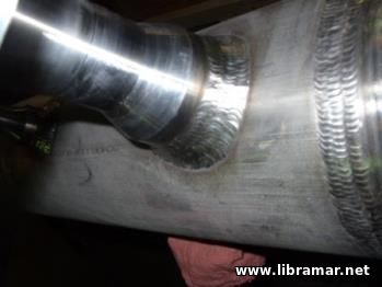 stainless steel weld layers which come in contact with the carbon steel. stainless steel weld layers which come in contact with the carbon steel.
When butt welding stainless clad steels, the carbon steel side is usually welded first with the appropriate carbon steel filler metal; particular care must be exercised to prevent the carbon steel weld deposit from impinging on the stainless steel overlay. The second side is then welded with a nickel-rich stainless steel filler wire such as type 309 or 310. If the carbon steel layer is relatively thin, the entire weld may be made with the 309 or 310 filler metal. Similar procedures are usually used for welding other clad carbon steels; i.e., deposition of carbon steel filler metal on the cladding is avoided, and a filler metal that is compatible with the cladding and the underlying base metal is used.
Steel to Aluminum
When joining steel to aluminum consideration should be given to the possibility of galvanic or crevice corrosion. Galvanized and stainless steel fasteners have been used to join steel to aluminum by mechanical means using rivets or fasteners. Aluminum is not 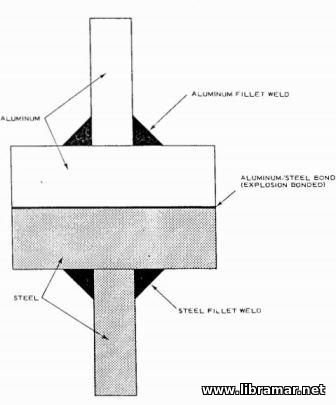 weldable to steel by conventional welding methods. To effect welded joints between aluminum and steel an inter-mediate composite plate material consisting of an aluminum and a steel layer is used. The bond between the aluminum and steel in the composite aluminum-steel plate, is made by special manufacturing processes such as explosion bonding. weldable to steel by conventional welding methods. To effect welded joints between aluminum and steel an inter-mediate composite plate material consisting of an aluminum and a steel layer is used. The bond between the aluminum and steel in the composite aluminum-steel plate, is made by special manufacturing processes such as explosion bonding.
Each plate side is then welded to similar material to form the configuration shown on the picture. This type of joint can be used for many purposes where an aluminum structure fastens to a steel structure. Familiar applications are the joint connecting the upper aluminum skirt plate and the lower steel skirt plate on some LNG carriers and the connection of aluminum deckhouses to steel decks. This type of connection has certain advantages in weather areas as regards corrosion compared to bolted or riveted connections.
 A major change in ship construction occurred over 100 years ago when steel was introduced to replace iron and wood as a hull material. Subsequent important developments in materials and ship construction were the all-welded ship and the application of concepts of toughness for the prevention of the brittle hull fractures experienced with the all-welded steel ships of the 1940's.
Over the past thirty years, many new designs have been introduced such as container ships, liquefied gas carriers, high speed surface-effect ships, and mobile and fixed offshore structures. To meet requirements for such designs, high strength-to-weight ratio alloys and alloys intended for low temperature service have been introduced into shipbuilding. The complex networks of intersecting members in offshore structures require that consideration be given to material properties when the applied tensile loads are perpendicular to the plate surfaces. The increasing size of ships, such as the VLCC tankers, and the concern for economy, stimulated automation of fabrication processes.
The relatively simple concept of toughness developed to answer the brittle fracture problems in ordinary strength steel hulls required refinement and extensive development before it could be applied to the newer hull materials and structures. For some structures increased consideration had to be given to such factors as fatigue and corrosion. Accompanying all these changes, was an increased demand for the designer to provide for quality assurance by nondestructive methods. To meet the challenges presented by these new developments, the designer had to become familiar with metallurgy, welding engineering, nondestructive testing, and the materials sciences. An appreciation of the basic principles of these fields will provide more efficient and reliable hull designs through selection of appropriate materials, joining, and quality assurance requirements...
 Aluminum Alloy Applications
Aluminum alloys find use where their special attributes such as low density and high strength to weight ratio, corrosion resistance in certain environments or retention of toughness at low temperatures are of value. Development of inert gas arc welding processes has facilitated the use of aluminum alloys for various ship structural applications. Aluminum alloys are frequently used in superstructures of large ships and for the entire hull structure of some ferries and small boats such as those serving the offshore industry.
The low density of aluminum alloys makes them particularly attractive for applications where high strength to weight ratios are of particular concern such as in surface effect and hydrofoil craft. Since aluminum alloys increase in strength and maintain toughness as temperature decreases, they have proven particularly suitable for cryogenic services such as containment of liquefied natural gas. Details of compositions, properties and methods of inspection are contained in American National Standards Institute documents...
 In the course of the welding cycle three events occur:
- 1. Filler metal and contiguous base metal are melted and resolidify to form a fused connection.
- 2. The heat effect of welding subjects the adjacent base metal to a thermal gradient ranging from above the base metal melting point to ambient temperature. The heat affected zone, HAZ, and deposited weld metal then cool to ambient temperature. As indicated in the picture, the variety of metallurgical structures produced in this heat affected zone includes those exposed to the various temperatures which produce resolidification of melted base metal, grain growth, grain refinement, or modification of metallurgical microstructure.
- 3. The solidification of molten metal, as well as the metallurgical phase changes, induce plastic flow and develop residual stresses which may exceed the yield point in magnitude; thus resulting in structural distortion
Hot Cracking
When cracking occurs at elevated temperatures, the crack is usually intergranular, meaning between grain boundaries. Such 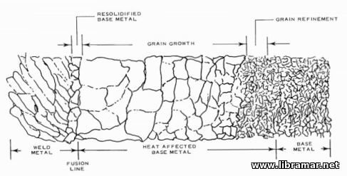 cracking is associated with excessive solidification and cooling stresses acting on constituents present at the grain boundaries which are relatively weak at elevated temperatures. The weakened grain boundary may consist of specific low melting constituents such as sulfides in steel. In other cases the deposition of a weld bead of unfavorable geometry may impose excessive cooling stresses on the hot weld deposit which has relatively low strength at elevated temperature. cracking is associated with excessive solidification and cooling stresses acting on constituents present at the grain boundaries which are relatively weak at elevated temperatures. The weakened grain boundary may consist of specific low melting constituents such as sulfides in steel. In other cases the deposition of a weld bead of unfavorable geometry may impose excessive cooling stresses on the hot weld deposit which has relatively low strength at elevated temperature.
For example, in submerged arc welding, weld beads such as those shown in the picture, would tend to form a center section which solidifies last and remains at an elevated temperature after the surrounding metal has solidified and cooled. The low strength at the grain boundaries of the material at elevated temperature is inadequate to resist the thermal stresses, and hot cracking occurs. Such cracking, can usually be readily prevented by changing weld parameters to produce a bead of more favorable contour.
Cold Cracking - Hydrogen Cracks or Delayed Cracks
The role of hydrogen is an important consideration in the welding of ship steels. Hydrogen-bearing compounds such as water or organic compounds present on the filler metal surface, in electrode coverings, or on base metal surfaces may dissociate in the welding arc to form atomic hydrogen.
The atomic hydrogen penetrates and is highly soluble in molten steel weld metal and the zone of adjacent heat affected steel which has been transformed to a phase known as austenite; the austenite 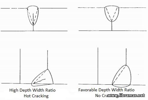 forms when the heat affected zone of a steel is heated above a critical temperature, (approximately 900°C (1,640°F), for structural steels. forms when the heat affected zone of a steel is heated above a critical temperature, (approximately 900°C (1,640°F), for structural steels.
As the solidified weld metal and austenitized heat affected zone cool to ambient temperatures, they are transformed into non-austenitic phases which release most of the dissolved hydrogen from solution, since hydrogen is practically insoluble in these phases.
When hydrogen is released from solution in the presence of a hard zone in the microstructure and a high residual stress field, a condition known as hydrogen cracking may occur. Since the time of such cracking varies from immediate to several days or weeks after the completion of welding, the phenomenon is also known as delayed cracking.
The tendency for such cracking varies directly with the magnitude of:
- 1. hydrogen concentration,
- 2. local metal hardness,
- 3. residual stress.
Hydrogen delayed cracking is the most important and troublesome form of cracking encountered in welding of the higher strength ship steels.
 End Launching
The vessel is ordinarily launched from the building position. The vessel's weight is transferred from the keel block, bilge crib and shoring building supports to the launching cradle. The cradle is supported on one or more ground ways which extend longitudinally under water. Attachments between sliding and ground ways prevent movement of the former. Restraining attachments may be burn off sole plates or triggers, release of which allows the cradle-supported vessel to slide down the ground ways under the influence of gravity and enter the water. As the stern acquires buoyancy, it lifts, and when this happens the ship pivots about its fore poppet. Checking of the sternward motion may be required to prevent grounding of the vessel on an opposite bank or shoal.
Side Launching
If the vessel is supported by a translation system, on arrival in the launching position the vessel's weight is transferred to the sliding ways or sleds resting on ground ways perpendicular to the vessel's centerline. If the vessel is built in the launching position, its weight is transferred as described above for end launching.
Floating Dry Dock
Varying deformations due to changes in solar radiation, air and water temperatures and varying loads, as well as the absence of a horizontal reference plane, makes a floating drydock unsuitable for the new building of vessels of any great size or weight.
Ground Supported and Floating Platform
The platform, which is essentially a floating drydock, is ballasted to rest on a horizontal underwater pile-supported grid, or in another version, has one side or one end of the platform temporarily connected to, and aligned with, the shore. The vessel is moved onto the platform, the inshore wing walls of the platform being temporarily removed if the vessel is moved transversely. Alignment between shore side and platform rails, tracks or ways is maintained by the relative fixity of platform deck and shore. If only side or end sup¬port is provided, the platform must be progressively dewatered as the vessel is moved on to it to keep the platform deck horizontal and aligned vertically. Even if the platform has the overall support afforded by a grid, progressive dewatering may be required to reduce piling loads if a heavy vessel is being moved onto the platform. With the vessel centered on the platform, any removed wing walls are reinstalled and ballast tanks are dewatered to float the platform clear of any submerged or above water supports. The platform is moved to a dredged area of enough depth for it to operate in a conventional floating drydock mode and submerge sufficiently to float the vessel being launched.
 The launching of a newly constructed vessel is deservedly considered one of the most critical events in the whole building process and one that is potentially hazardous if the movement of the large, yet fragile, mass that is supported on a comparatively frail structure is not properly planned and executed. Configuration of design and selection of materials for suitability and strength and the control of, and making use of, the natural forces of gravity, buoyancy, water resistance and friction is, in essence, the art of ship launching. A properly engineered launching can be accomplished safely and efficiently. The development of this engineering plan is one of the most important tasks facing the shipyard naval architect.
At the time of receipt of a request for a proposal, major preliminary calculations are commonly made in order to verify that the vessel can be constructed and launched, in one or mоге pieces, using facilities existing or suitably modified, and this would typically allow to make some basic planning. Following contract award, further calculations are prepared to exactly locate the vessel on the building slip, determine forces acting on the ground ways, cradle and ship, and to provide a basis for the design and delineation of the launching arrangement.
 Ordering of Steel
Mill orders are normally prepared by the drawing room, with the plate sizes being lifted from ship plans or plating models or, alternatively, obtained directly from computer printouts. Each piece of steel is assigned an identifying mark on the plan and on the bill of material. Plates to be severely hot-formed are ordered somewhat thicker than the required size in order to allow for the thinning down that occurs during the forming process.
There are price extras for very narrow, very wide and odd gage plates. Plates in the 1830 to 2286 mm (72 to 90-in.) width range are the least expensive per unit weight. The most economical sizes for the shipyard are determined after considering all related factors including the number of welded seams. Selected even-gage plates cost less per unit weight. In English units, the even gages are normally every 1/32 in. for plates up to 1/2 in. thick and every 1/16 in. for plates over 1/2 in. thick. In metric units, even gages are normally every one mm for thin plates and every two or more mm for the thicker plates.
The exact called-for grade of steel may not be obtainable for some ship repairs or when a small amount of steel or a special grade of steel is required. It is then necessary to obtain a proper substitute. Specific classification society approval of the substitute might be required, especially when ASTM and other non-ship grades are involved.
There has been little effort to increase the amount of standardization of plate or shape sizes beyond that normally adopted because such increases have been considered to be of little, if any, economic value.
Design work on structures incorporating large castings or forgings, such as a stern frame, is started early due to the long lead time required for these large items./p>
|